Home
Home


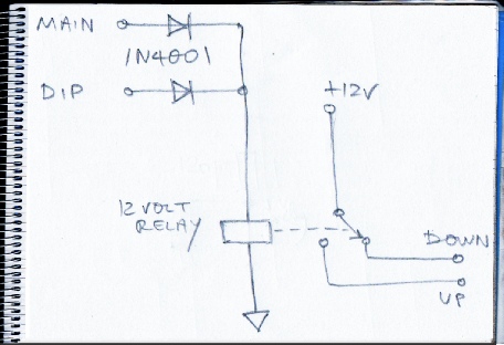
This (on the left) is the simplest circuit to do the job, I think. Supply to the main and dip headlights are connected to a relay via diodes which prevent the main and dip simply being shorted together (and, therefore, both on at the same time).
The relay then switches current from the down to the up circuit as required.
One disadvantage would be that it would be impossible to flash the lights as the light units would go down as soon as the flasher stalk was released. Also, perhaps, if there were a brief gap between dip and main when switching between the two, then again the lights would go down (once they start, they have to finish!)
(Causing a delay to lowering is the purpose of the fabled Pektron unit. See here for my analysis of how it works.)
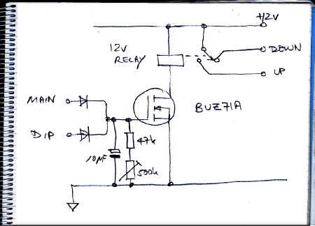
This circuit (left) uses a mosfet to delay the lowering of the lights, after they have been finally turned off, for an adjustable period (in the region of 4 seconds give or take). As long as the lights are re-
The 10 micro Farad capacitor charges up and when the headlights are turned off it discharges through the resistors (the mosfet gate draws a minuscule current so it has little effect). Eventually, the gate voltage is so low that the current through the relay coil is insufficient to hold the contacts closed and the relay switches over to supply current to the down circuit. I probably should have included a diode across the relay coil! It turns out that this circuit is very similar to the Pektron except it uses a bipolar transistor rather than a mosfet.
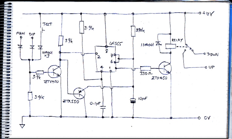
The circuit with the mosfet might be a bit imprecise in that the point at which the relay coil loses the ability to hold the contacts closed might depend on a lot of things such as vibration, temperature etc. This randomness probably doesn’t matter for this application. However, I offer two other (admittedly much more complicated circuits) which offer much more precise timings.
The first is shown above. The timing is courtesy of the 555 timer, an IC that dates back to the early 1970s but is still extremely handy for the amateur experimenter. The 390k and 10 micro Farad capacitor form the timing network (when a timed period starts, the output, pin 3, goes high and the capacitor charges up through the resistor till it reaches 2/3 of the supply voltage, then the output goes low again). The timed period is initiated by pin 2 going low. This happens when 12 volts from the headlamps is applied to the ZTX450 farthest left (when the input to this goes high, the output connected to pin 2 goes low. Any time pin 2 is low, the ZTX550 (pnp) transistor shorts out the timing capacitor preventing the timing period from finishing (know as re-
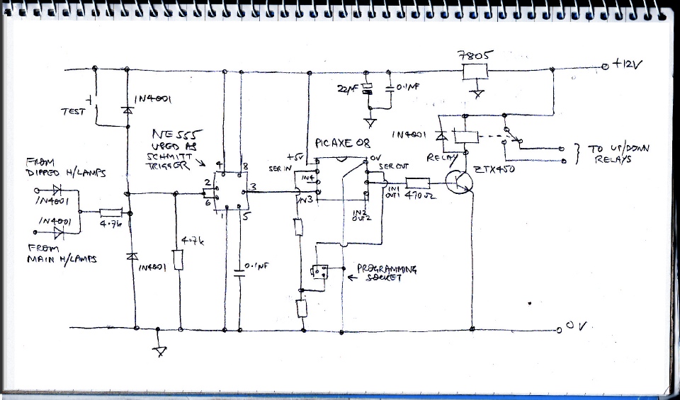
The final circuit below uses a Picaxe microprocessor which is very easy to program in circuit with a simple Basic-
The circuit uses a 555 connected as a Schmitt trigger to provide a clean on or off (0 or 5 volts) to an input of the Picaxe. The picaxe is loaded with a simple control program
Although I have this circuit in my TR7 and I have never had any problems it should be pointed out that the Picaxe does have some problems in my view. From time to time it can crash -
Details of the Picaxe software are on the next page.
Headlight circuits 2
(NB I have a, hopefully, improved version of this controller here… which also controls the speed of one of the motors so that they rise up in unison! Read on for my original idea.)
(NB I have a, hopefully, improved version of this controller here…)
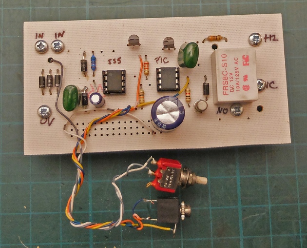
Completed pcb for the Picaxe based circuit shown above.
Push to test switch
Programming socket