


 Home
Home

Under construction
Improved headlight controller
I became intensely dissatisfied with the way one of the motors driving my pop up headlights delivered its light into the up position a little slower than the other and I became determined to do something about it! Not being one to shy away from complication when a simpler solution would do, I decided to redo the circuit which I used to replace the Pekon unit in the original electrical system. Although I could have tried introducing a suitable series resistor into the supply for the faster motor, I decided to use a circuit which can control motor speed with pulse width modulation (pwm) which will enable motor speed to be easily adjusted. I am going to use an Adafruit Trinket microcontroller which has already featured in a number of my projects (fuel gauge, light level controlled security light, keyboard emulator etc.) The Trinket is small, cheap and can be programmed using the Arduino IDE with which I am reasonably familiar.
The system needs to detect the headlights being on or flashed and connect power to the headlight up circuit. When the lights are off, power needs to be connected to the down circuit. To prevent the lights going up and down when flashing, the circuit needs to delay the lowering of the lights a short period of time.
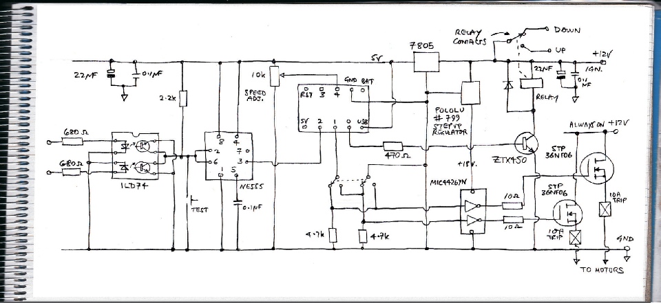
I have connected the supply to the dipped and main beam to a couple of opto isolators. This achieves a level shift from 12 volts to the 5 volts used by the Trinket and avoids voltage feeding between the main and dipped circuits. I am pretty sure I could have connected the collectors of the optos directly to a Trinket input but to be on the safe side I interposed a Schmitt trigger between the two. A Schmitt trigger provides only two outputs, low or high, with a rapid transition between avoiding any glitches if the input is a bit messy electrically speaking. Optos with Schmitts are available but I didn't have any in my box of bits so I used a 555 timer which can be wired to do the job.
The up and down circuits are controlled with a SPDT relay. The motors themselves are supplied with power via a couple of MOSFETs driven by suitable driver chip to enable pwm control. If the loads are connected between the MOSFET's source and ground, as is the case here, then a higher than supply voltage is needed to drive the MOSFETS. Otherwise, the MOSFETs will not be fully turned on, voltage will be lost, the motors will not run at full speed and the MOSFETs will get very hot. To provide this over voltage, I have used an adjustable boost regulator (Pololu #799). I have set this to generate 18 volts. The on board pot used to adjust the voltage is very non linear and is very sensitive to movement at this output voltage. I slightly worry that vibration might cause the voltage to significantly alter in the future.
Circuit description
Circuit
Trinket limitations
I had originally intended to drive both motors with separate pwm from two of the Trinket pins. This would have left the remaining three GPIO (sort of) pins for trigger (digital) input, speed setting from the analogue reading of a 10k pot and a (digital) output to drive the up/down relay. As you can see from the details on the Adafruit site, not all digital and analogue functions are available from all the pins. I had to allocate pins 0 and 1 to pwm, 4 to reading the pot, 2 as the trigger input and 3 to drive the relay. Pin 3 is the problem. This pin turns on and off during boot up and this in turn triggered the up/down relay which would have raised and lowered the lights when the ignition was turned on which was not acceptable. Perhaps I could have used pin 3 as the trigger input and pin 2 to drive the relay but in the end, I used pin 0 as a digital output to drive the relay. I use a switch to select which motor receives the pwm and which receives full power. I keep two MOSFETS which avoids having to use a 10 amp rated switch. I have used an inverting driver (a MIC4426YN which was what I had in my box of bits) so the pwm is also inverted when it comes to programming -
Next, contruction and software…
Before…
After…


Switch selects which motor gets controlled
To main and dipped head lamps

For further details of how the pop[ up mechanism works, see here…