


Under Construction
The Pektron unit explained?
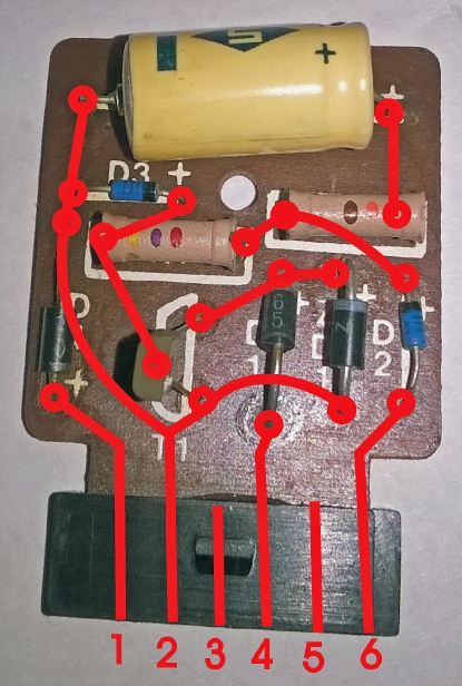
Left is a picture of the “works” inside the Pektron unit (thanks to Jon for the picture of his unit). I have superimposed the tracks on the rear of the pcb onto the front in red.
I have arbitrarily numbered the contacts 1 to 6 (two, 3 and 5, don't connect to anything).
We can deduce the circuit which I have drawn out below. Component types in brackets are my suggestions for easily available replacement parts.
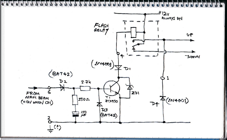
This is how I think it works. Contact 6 connects to the main beam. When it is on, 12volts is fed through D2 and the 330 Ohm resistor into the 150uF capacitor which very rapidly charges up to 12volts. This causes current to flow via the 2.7k Ohm resistor into the transistor which “turns on” causing current to flow through the relay coil, closing the contacts which raise the light units.
When the main beam is turned off, the 12 volts on the capacitor keeps the transistor turned on so that the relay stays on and the lights remain up. However, the transistor draws a small electric current through the 2.7k and 330 Ohm resistors which discharges the capacitor within a short time. When the voltage drops to, perhaps, a couple of volts or so, the transistor does not pass enough current through the relay coil to keep the contacts closed and the light units go down.
D2 stops the capacitor discharging through the lighting circuit and is just a low voltage, low current diode (an obsolete gemanium type says Jon -
Note, it seems to me that logic dictates connection 2 must be connected to the chassis. However, this is not shown on the circuit diagram in the TR7 Haynes manual.
All these components are available from many suppliers, for example, Ebay.
The Pektron unit causes a delay in lowering the headlamps so allowing the lights to be flashed. Not all TR7s were fitted with these units. Whether it is useful to be able to flash pop up headlights is a moot point in my opinion as headlamp flashing tends to reflect an urgency which is blunted by the time taken to raise the headlamps in the first place.
However, if you have one and it’s faulty, it can cause the headlamps to malfunction so something needs to be done about it.
When I got my TR7 about twelve years ago, the pop ups did not pop and I had to drive about with the headlights permanently raised. This made me feel a bit of a second class citizen so I decided to try to fix it.
I didn’t trust any of the wiring, relays etc. and decided to replace the lot with my own design. Being a fan of electronics this was fun for me but most people want their headlamps fixed as soon as possible and, perhaps, faithful to the deign of the TR7 as manufactured. So if you want to repair your (new ones are not available) perhaps the following will be helpful.
Testing whether a fault is caused by the Pektron
Please note I haven’t tried this myself so no guarantees…
If you want to test whether the fault is with the Pektron unit, remove the unit and use a thin wire to touch (cautiously) contact 4 on the socket to the chassis (zero volts). This should close the flasher relay (you should hear a click) and raise the lights. When the wire is removed they should go down again. If that doesn't happen, for both motors, perhaps the headlamp circuit breaker is faulty. (There don't seem to be any fuses shown on the circuit diagram.) If only one works then dirty contacts on the limit switches in the motor, faulty diodes in the motor switches or a faulty motor relay (run/stop) might be the cause. Of course, dirty connectors could also be a cause.
(Disclaimer! I have not tried out or tested any of this on my car!)
Email me with comments or corrections! (mr-