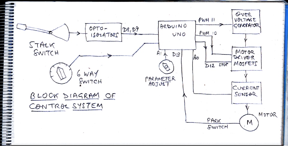
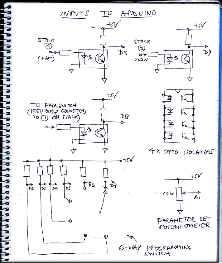
The sketch above shows a block diagram of my system with the assignment of ports on the Arduino. I could have used the six-way switch in a potential divider circuit of five resistors between 5 volts and zero volts thus outputting a voltage to an analog port which depended on the position of the switch. I chose to use 6 digital ports but I don’t know why! (As I write this I notice I only needed 5 as when all 5 are showing 0, the switch must be in the unconnected position.)
The mosfet driver and current sensing circuits are on the next page…
 Home
Home