 Home
Home


A mosfet in the position shown with the load in the source needs its gate driven to about 18 volts to completely turn it on so that its source drain resistance is at its lowest possible value (a small fraction of an ohm). Otherwise, power will be dissipated in the mosfet which will heat up and volts will be dropped and the motor will not run at full speed or power.
The 18 volts is generated using a square wave generated by the Arduino (50% pwm) and boosted in power by the MIC4422 power amplifier. A voltage doubler circuit raises the voltage which is then regulated to 18 volts by the LM317 regulator. (As I recall, the MIC4422 is only rated for 20 volts so this is needed.)
Pwm from the Arduino is fed to the mosfet via another MIC4422. As I understand it, a high drive current is require for square waves due to the high capacitance of a mosfet’s gate so you can’t feed it straight from the Arduino pin.
Another mosfet is turned on to short the motor to stop it rapidly when it needs to park. This can be fed straight from an Arduino pin. (Don’t let the software turn both mosfets on together otherwise there might be a big bang!)
The current sensor uses an ACS756 integrated circuit which produces a voltage of 2.5 volts with zero current and proportionally lower or high voltage depending on the magnitude and direction of the current. I use an LS324 to amplify the output a few times to get a better resolution from the Arduino’s analog port. Adjust the output of the LS324 to 2.5 volts with zero current passing through the ACS756. (Note, I have written AC8756 on my sketch rather than ACS756 which is just plain wrong!)
Next are construction details and software.
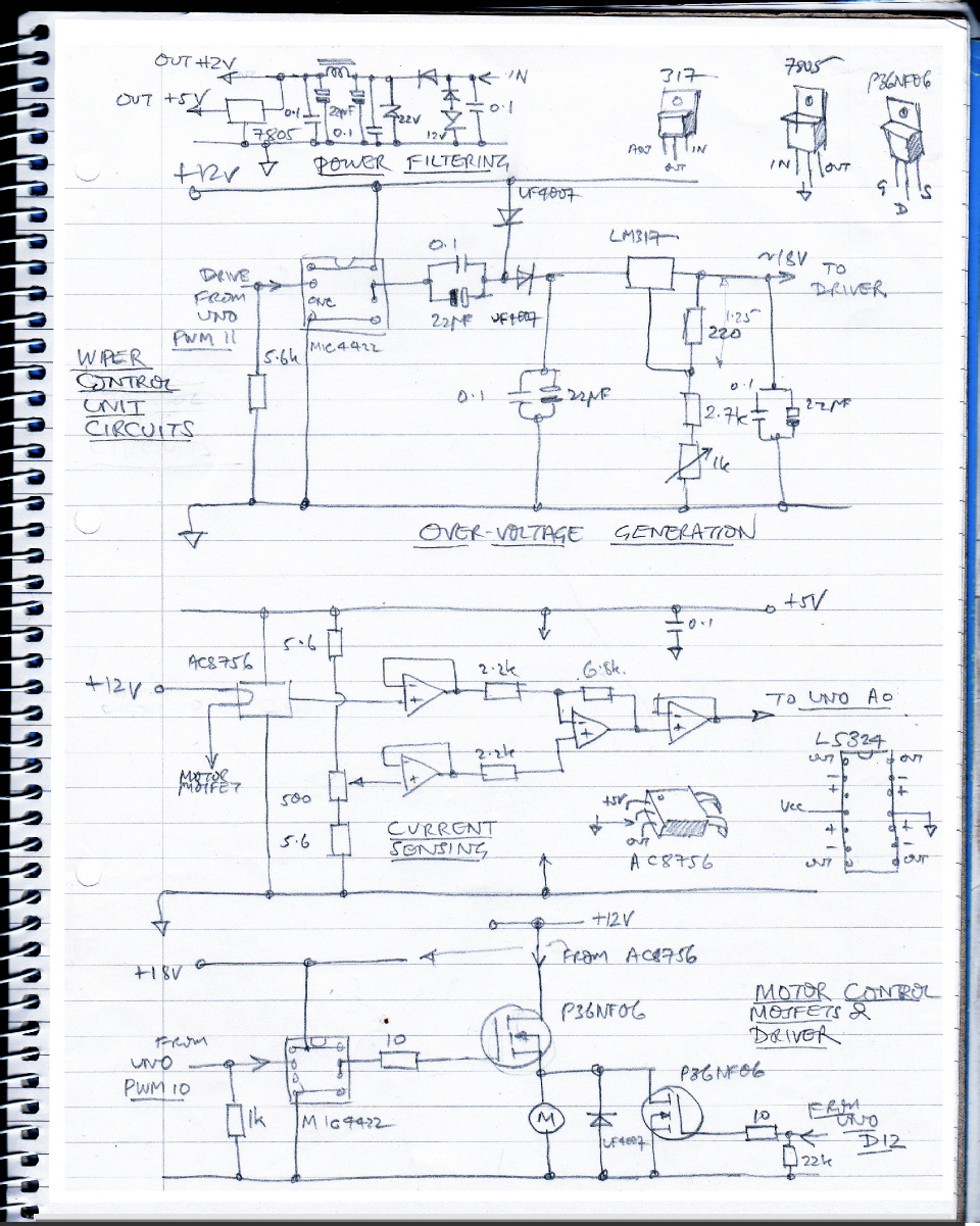


Wiper control circuit 2