
Under Construction
Wind direction indicator 4
To prevent the ingress of rain water where the wind vane shaft enters the box, I needed a cylinder sealed onto the shaft which fits over a cylinder sealed to the box where the shaft emerges.
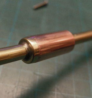
Suitable bits lying around the workshop were a piece of aluminium tube which fitted inside a piece of 15mm copper plumbing tube. To fix the tube to a base which could be screwed to the case I had to use Lumiweld which is a low temperature solder which bonds to aluminium (which lead/tin soft solder does not). I drilled a hole in a small piece of aluminium sheet which was a tight fit for the tube. I prepared the aluminium where the Lumiweld was to be applied by brushing the surface with a stainless steel brush. This removes the oxide layer on the surface of aluminium (this is present on all aluminium, protecting it from further corrosion). The assembly was then heated up with a butane torch until the Lumiweld melted when touched on the surface. If it fails to wet the surface, it can be scrubbed in with the brush or a piece of stainless steel wire. The idea is to form a fillet round the joint (the Lumiweld will not flow into tight joints like other solders and brazing materials do. I suspect the joint is not too strong but is more than adequte for the present purpose.
Left, I needed to mark on the box lid where the shaft would be. A pencil of the right length was a good fit in the 8mm hole. I taped a piece of paper in the lid and put the lid on the box. The pencil left a mark where the shaft would emerge. For the time being while things were being located in position, I drilled a 2.5mm hole in the lid in the position indicated by the pencil.


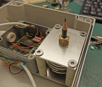
Below left: next I drilled four 2.5mm holes in the existing top plate, prepared another piece of aluminium the same size as the top plate and used the original top plate as a pattern to drill corresponding holes in the new plate. I used an 8mm drill to mark through the centre of the original top plate onto the new plate. I just drilled far enough to leave a dimple which I used to guide a 2.5mm hole. I then temporarily screwed the second plate by the 2.5mm centre hole to the lid and drilled the other four 2.5mm holes into the lid using the plate as a pattern. I then enlarged the centre holes to 8mm and the other four holes to 6mm in both plates and the lid. I installed four bolts and separated the plates with three nuts. This provided clearance for the brass top bearing (a cut down plumbing compression joint, you will, perhaps, remember).
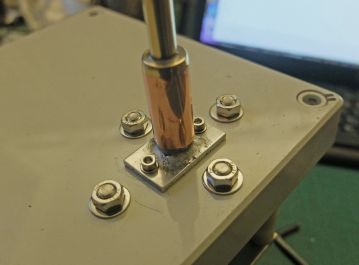
Above right: I assembled the “works” and the lid and positioned the Lumiwelded aluminium part on top. To do this, I temporarily installed the 8mm rod and used a conveniently sized piece of tube which fitted over the rod and inside the aluminium tube, which centred the assembly. I then drilled 2.5mm fixing holes which I subsequently tapped out to M3 thread.
Left: The shaft and weatherproofing assembled. You may remember a 3mm screw held the shaft to the Grey disc assembly. I filed a small flat on the shaft to ensure the screw could not slip.
Some silicon sealant under the aluminium plate and round the nuts and bolts will be required when final assembly takes place but for now, this part of the project is completed other than for the vane itself…
Next, I needed a sleeve on the shaft which would fit over the aluminium tube, described above, which would prevent rainwater ingress.
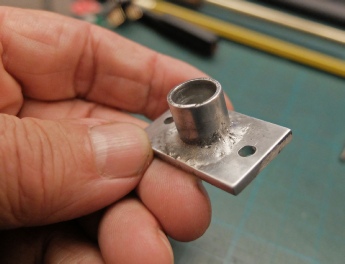
I took a piece of 3mm brass sheet and placed a piece of 15mm plumbing tube on it. I placed the assembly on a piece of firebrick ready for silver soldering. I blobbed on some suitable flux paste round the joint and heated the whole thing up. At first the water in the flux evaporates leaving a powder. When the powder liquefies and flows round the joint, the temperature is probably right (at this point the brass and copper are red hot). Apply the silver solder rod to the joint avoiding heating it directly with the flame of the torch. When it melts, the solder instantly flows round the joint and will also flow into any tight spaces (close joints are what silver solder is good for, gap filling is not its strong point!)
Then I used a large drill inserted into the tube to mark the centre as above and drilled an 8mm hole. I then cut, filed and sanded the brass down to the same diameter as the tube. Finally I soft soldered the brass to the shaft. I used a suitable piece of tube inserted over the shaft and into the open end of the tube to keep things parallel while I did the soldering.
Next, I am going to add an anemometer to measure wind speed.
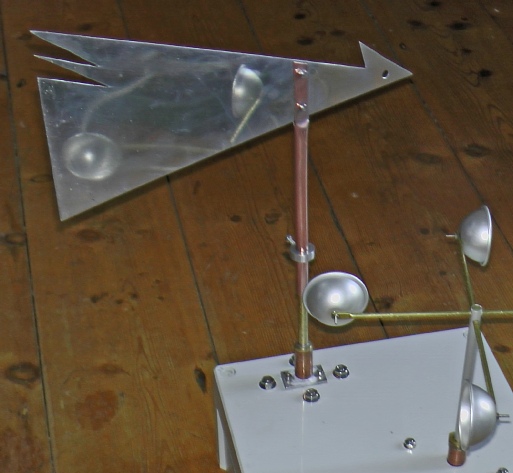
I spent rather a long time trying to come up with something really creative for the design for the vane but came up with nothing immediately! In the end I just cut out a piece of thin aluminium which looks like a cross between half an arrow and something which might look a bit like a modernist bird if you half closed your eyes! However, later I went a bit mad with the 3D printer (see below).
To fit this onto the brass rod, I took a piece of 10mm copper tube which is a reasonably snug fit over the 8mm diameter of the brass. I cut a slot in the tube, fitted a piece of aluminium in the slot and squeezed it flat in a vice. I drilled a couple of 3mm holes through the copper and aluminium and secured the parts together with stainless steel screws and nyloc nuts.
Next, I sliced off a section of ¾ inch diameter aluminium circular bar and drilled a 10mm hole through. I drilled a hole in the side and a corresponding hole in the copper tube. I tapped an M3 thread in the aluminium so that when the aluminium collar was slipped over the copper tube, a screw could be used to lock the vane onto the brass rod. This enable the vane to be set so that the rotary encoder outputs “0” when the vane is pointing (say) North.
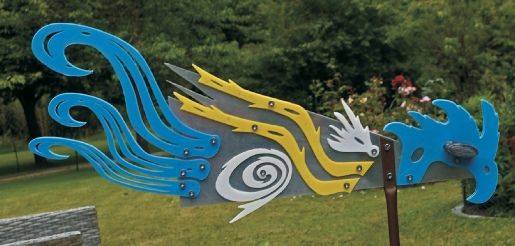
Later the Modernist bird became this Post Modernist extravaganza. I can’t quite make up my mind about this. My wife characterised it as “eccentric”!
Lead balance weight.