


Under Construction
Anemometer 1
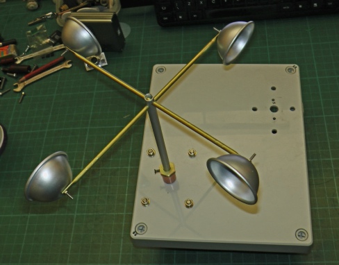
Left is the anemometer at a fairly advanced stage of the making it is a hemispherical cup anemometer similar to the type invented by John Thomas Romney Robinson. The hemispheres are from eBay described as “3D Aluminum Ball Sphere Bath Bomb Cake Moulds” and are 4.5 cm size. The hemispheres are fixed to arms made from 4mm diameter brass tube available from B&Q (or K&N Metals at model shops). The ends are crushed flat in a vice and drilled so that the hemispheres can be attached by M2 stainless steel nuts and bolts.
The shaft is 8mm diameter aluminium tube (again from B&Q). 4mm holes at right angles are drilled in the end to take the brass arms. Obviously, the arms need to be through the holes in the tube before the second end is flattened otherwise they won’t go through the hole!
Eventually, when I have aligned everything, I will pour a little Araldite down the top of the aluminium tube to lock everything together and seal the tube against water ingress.
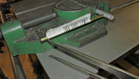
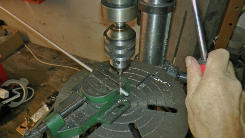
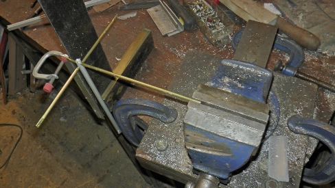
In order to drill the second hole at right angles to the first, I have to make sure the tube is horizontal in the vice. I use callipers to check that both ends of the pipe are the same height above the table.
Then I can drill the hole. To get the hole in the centre of the tube, I use a drill bit that just fits between the cheeks of the vice to make a little mark in the tube, Then I change over to the 4mm drill bit and make sure it drills into the mark I have just made.
When crushing the ends of the tubes, I need to ensure they are in the same plane as far as possible. In the picture you can see I have clamped a flat piece of metal to the end already flattened and am checking that the tube is twisted so that it aligns with the set square on the bench. This will be good enough (I hope!)
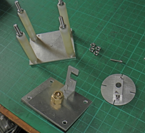
Left shows most of the parts needed to make the base for the anemometer. The top and the bottom are made from 3mm aluminium sheet and are separated by four nylon stand-
The top bearing is made from an 8mm plumbing straight coupler with the central stop drilled out to 8mm. The bottom bearing is a dimple formed in the base with a counter-
The bracket takes the optical sensor (see below). The disc, made from 1mm aluminium, with its four slots interrupts the beam as it turns.
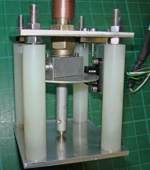
Left shows the assembly. The optical switch, type OPB370T55 can be seen on its bracket.
The brass lower bearing is held in with grub screw (which is not in place in the picture).
The slotted disc is screwed to a piece of 12mm square aluminium which is drilled to 8mm to fit the shaft. A hole drilled and tapped to M3 has a screw inserted to hold the disc in place on the shaft. A washer gets the disc to run in the centre of the switch. It bears on the brass top bearing with just a little clearance to avoid friction as the shaft turns while preventing the shaft from coming out.
Next, circuit and testing.