


Under Construction
Anemometer 2
The software below runs on an Adafruit Feather connected to the Anemometer by I2C. The signal from the optical switch is connected to pin 3 on the MCP23017 port expander chip. The software waits for a change in state of the optical switch (pin 3 seeing a high to low or low to high -
Of course, the device will have to be properly calibrated calibrated. I envisage clamping it to my car and driving at various speeds and taking note of the output from the device. Hopefully a graph of number of counts against speed will result in a smooth curve from which intermediate values can be deduced. This will not be desperately accurate as airflow close to the car will not necessarily be at the relative speed indicated by the speedometer quite apart from doubts about the accuracy of the speedometer itself. I may use my TR7 whose speedometer I calibrated using my sat nav. (Original speedometers on cars, I believe, are required to indicate slightly fast.)
The software below averages the last five readings to give a smoother (but less accurate?) output. The number is output over serial.
Test software
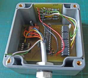
The circuit for the anemometer is identical to the wind direction circuit except that the reflective opto-
The 7555 for the anemometer fits in this socket.

Circuit
// ***************************************
// * wind_speed_test4 tests wind speed *
// * By Julian Rogers 11.11.18 *
// ***************************************
// integrates disc pulses over 2 secs
// libraries
#include <SPI.h>
#include <Wire.h>
#include <Adafruit_MCP23017.h>
byte b0, b1, b2, b3, b4, b5, b6, b7, num, old_num = 0, oldB4 = 0;
long count = 0, ave = 0;
unsigned long period;
int i = 0, counts[5];
Adafruit_MCP23017 mcp2;
//-
void setup() {
delay(1000);
Serial.begin(9600);
Wire.begin();
mcp2.begin(2); // use address 0x22 (0,1,0) rather than default for rain gauge
mcp2.pinMode(3, INPUT); // sensor on pin 3
}
//-
void loop() {
//start counting
count = 0;
period = millis();
while(millis() < period + 2000){
b4 = mcp2.digitalRead(3); // speed sensor
if(b4 != oldB4){
count++;
}
oldB4 = b4;
}
counts[i] = count;
i++;
if(i == 5){
i = 0;
}
for(int ind = 0; ind <= 4; ind++){
ave = ave + counts[ind];
}
ave = ave / 5;
Serial.println(ave);
//Serial.println(int(count*3.75)); // count is close to number of pulses in 2 secs * 2
// 4 pulses per rotation so rpm = count*30/8 = count*3.75
// wind speed is of the order of rpm / 2 or count * 1.875
}
//-
Next, a Python program which presents the output on a representation of a dial gauge.