


Under Construction
Wind direction indicator 3
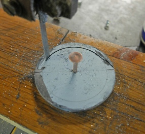
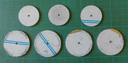
The first job (left) is to cut seven pieces of 3mm aluminium sheet 65mm square. The centres are marked, centre-
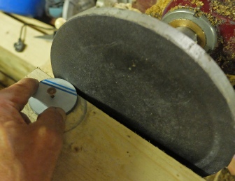
The minimum diameter that can be cut by this method depends on the width of the blade and the set of the teeth which creates the clearance for the blade as it it cuts. By the way, in the picture, I am cutting the smaller diameter on the disc which will produce the non reflecting section. The picture above right shows a similar procedure with the nail etc to sand away the saw tooth marks. The disc should not press too hard on the sander. I do this in two stages, first with 100 grit carbide then with 240 grit.
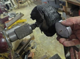
Having cut the discs, I polished the edges of the four code discs with a mop (above centre) loaded with brown cutting/polishing compound (“Tripoli”). I felt that a polished edge would reflect the light more efficiently and consistently. Later I wondered if the polished edge on a convex curve would actually reduce the light reflected to the photo-
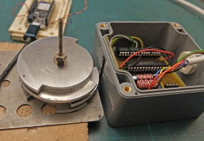
(Left) I bolted the assembly together and, locating the head of the screw in a suitable hole in a drill gauge, I twiddled the discs in front of the sensors and checked that some reasonably consistent results were generated by the program running on an Adafruit Feather.
It dawned on me that an 1/8 inch diameter rod would not be strong enough as an axle. I found a length of 8mm diameter brass rod which looked more satisfactory. However, now I had to enlarge the 1/8 inch hole to 8mm keeping it centred as accurately as possible. I didn’t think just sticking it in the drill press would do.
The answer is to drill using a lathe. Unfortunately, I don’t have a metal working lathe, only a wood lathe. These tend to be much less accurate and possibly too fast.
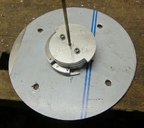
Anyway, I gave it a go! I cut a disc in 3mm aluminium the diameter of my lathe face plate and drilled an 1/8 inch hole in the centre. I located one of the code discs onto the centre of the new disc with a short piece of 1/8 rod and drilled a dimple through each of the bolt holes in the code disc. I then removed the code disc and used the dimples to drill 2.5mm holes through the disc. I put an M3 tap in the drill press chuck and applied it to the holes and turning the tap by hand, cut M3 threads into the disc. (You can’t cut threads accurately square into aluminium as thin as 3mm just using a hand wrench on the tap.)
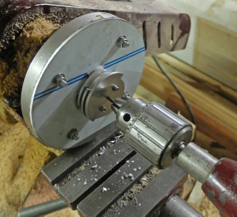
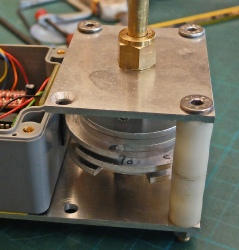
I loosely bolted the discs to the faceplate, (above left), put a piece of 18 rod in a chuck in the lathe tail stock and used this to accurately centre the discs before tightening the bolts securing the assembly to the faceplate (top right).
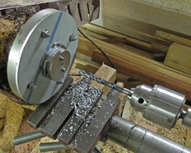
I put an 8mm drill in the chuck and advanced the chuck as steadily as possible (left).
One fear was that the drill would grab into the aluminium and pull the drill chuck out of its Morse taper. I pulled back on the chuck as hard as I could to try and prevent this happening. In the event the speed of the disc was much faster than I would have liked but I seemed to have got away with it and cut a clean and reasonably accurate hole. I could have saved myself all this bother if I had originally drilled the discs 8mm instead of 1/8 inch and used an 8mm pivot on the band saw and the sanding procedures! Oh well, future lives as they say!
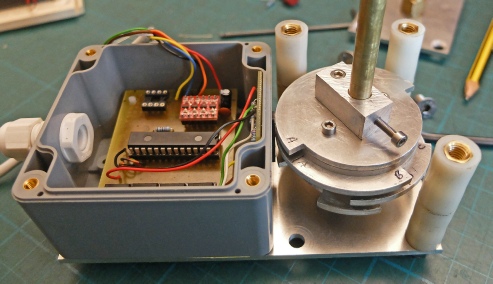
Next was a chassis to hold everything together. This comprises a large plate to hold the electronics and the bottom bearing of the code discs, a smaller plate for the top bearing and some stand off pillars I had in my box of bits which holds the two plates apart (some M6 threaded rod with some nuts would have done just as well).
I drilled a piece of 12x12mm aluminium bar with an 8mm hole. I drilled a hole to secure it to the discs and another, tapped to M3, to lock it to the bar.
The electronics were bolted to the base plated with holes big enough to allow a small adjustment. The spacing between the reflective surface is around 1mm.
The bearings are cut down 8mm pipe compression fittings (without the olive). The picture shows one of the pillars removed so that I can see more clearly what is going on during testing.
It turned out that the spacing between the sensors was a little more than 3mm and by the fourth disc, the error had built up to make the sensing a bit unreliable. I cut some shims from thin mylar. Two thickness (which was about 0.33mm) between each disc aligned the sensors with the discs to a reasonable accuracy.
Next, more construction.