


Under Construction
On these pages, I describe how to install a pair of 600 x 600 LED panels to light a rather dim hallway. However, I need to dim the panels somewhat as at 40 watts they are rather bright! I describe a way of doing that using a standard LED driver and some extra circuitry.
LED panels 1
Introduction
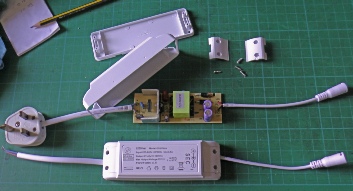
Above: what’s in the driver box which came with the panels. Looks similar to a switched mode supply.
We have a rather dark hallway with no external windows. My idea is to frame a couple of 600 x 600 LED panels on the ceiling and, perhaps, pretend they are skylights. The ceiling is quite low and as they stand, the panels are too bright so some dimming will be required. I had the idea of switching the two panels on and off at about 200Hz so that one was on while the other was off. That way I should only need one LED panel driver. 200Hz will be well above the production of noticeable flicker and hopefully, low enough to not cause RF interference. When you open them up, the LED drivers look like switched mode power supplies but set up to produce constant current rather than constant voltage. I was not sure whether chopping the output in the way I was proposing would upset the electronics but it was worth a trial.
A 555 timer producing an equal mark/space ratio pulse (on and off times the same) would be a start with mosfet power transistors to switch the panels on and off. A mosfet is like a switch controlled by the gate terminal. When off, the mosfet has for practical purposes infinite resistance between its source and drain terminals and when on almost zero resistance. In these conditions, the device dissipated almost no power (generates no waste heat) and so requires no heat sink.
Although you can maintain a mosfet in an on condition by applying, say, 5v to its gate with the gate drawing almost zero current, the gate has significant capacitance which needs to be charged up initially to the voltage needed to turn the mosfet on (it also needs to be discharged to turn the mosfet off). This is no problem when just turning something on and leaving it on and the output of a 5v microprocessor should be ok for this. However, turning it on and off 200 times a second is a different matter. The mosfet will end up hovering somewhere between on and off most of the time which means there will be a resistance between the source and the drain terminals and resistance means power dissipation (or waste heat, equal to I2R). Something with much more oomph than the output stage of a 555 or microprocessor is required, namely, a mosfet driver such as the MIC4426YN.
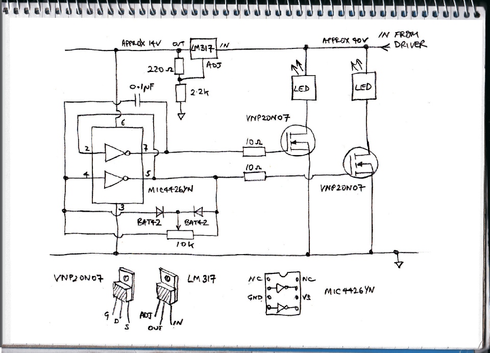
I started off with a 555 timer connected in equal mark/space mode. I connected the output to one input of a MIC4422YN dual mosfet driver and connected the output to the input of the other driver. Since the drivers are inverting, the outputs of the two drivers were 180 degrees out of phase, that is, when one was on, the other was off and vice versa. I connected the outputs to the gates of two power mosfets with an LED panel between each drain and the LED driver. I supplied the 555 and the MIC4422YN with 14 volts stepped down from the LED driver using an LM317 adjustable regulator (the maximum allowed input/output voltage difference on the 317 should be sufficient for this application). This worked fine on a bread board.
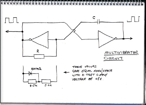
Then I remembered the NAND gate multivibrator circuit from way back when and realised I could use this to generate on/off pulses using the MIC4422YN and drive the mosfets at the same time saving a 555 chip (although this is hardly a big deal, it's good to try something different and avoid using a 555 in a project for a change!)
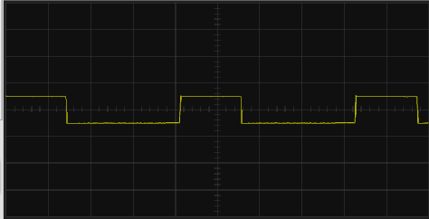
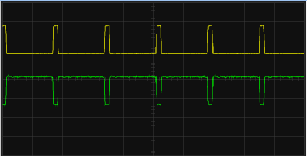
The trace on the right, top, shows the relatively short mark and long space using the circuit with just the R and the c. The trace below shows how, using the diode to change the value of R between charge and discharge, the mark and space can be equalised.
The circuit uses a capacitor which is charged and discharged through a resistor by the two drivers. The trouble with this circuit, I discovered was that the mark and space were not equal which means the panels will not be quite equal in brightness. However, by splitting the resistor into two and putting a diode in parallel with one of the resistors the effective value of the resistor in charge and discharge can made different and with the correct choice, the mark and space can be made equal. The required values are affected by the supply voltage, I think, but the LM317 should keep this stable enough. (If I were going for the ultimate in reliability, I would plump for the 555 circuit as its design is inherently stable and independent of supply fluctuations.)
I then thought about using a potentiometer to adjust the brightness balance between the two panels. By using two diodes, it is possible swing the two panels from dim to bright and bright to dim respectively through equal half brightness (one is dim while the other is bright, that is – differential dimming?). I thought that as one end of the hall tended to be darker than the other, a slight alteration of balance between the two panels might improve matters subjectively.
Sadly, it is not possible to dim both together in the same direction (other than both being half bright). The driver needs to see the equivalent of a normal load. If it doesn't have enough load, it turns off and on again leading to low frequency flashing (which could be unhealthy!) This means that you can't remove one panel and use the potentiometer to dim the remaining panel beyond half brightness.
This is not quite true, it will tolerate about half load before flashing (The driver runs at its usual temperature under these conditions so I have no reason to believe, at this stage, that running it in this fashion would not be reliable. Therefore, it remains a possibility if you have one panel that you want to run at half power.
you want a zero-
(It should be noted that this works with the driver I got with the panels. Other drivers might behavedifferently.)
Final circuit
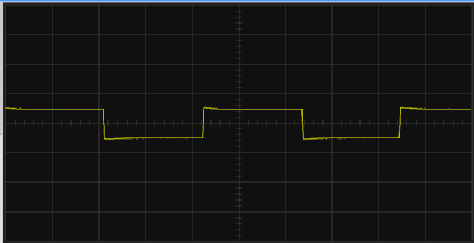
This trace shows a case where the panel responding to the top waveform will be dim (small mark, big space) while the bottom waveform will produce a bright panel (big mark, small space). However, they overlap so that the driver sees a constant full load (ignoring the relatively small rise time of each pulse -
Next: construction.
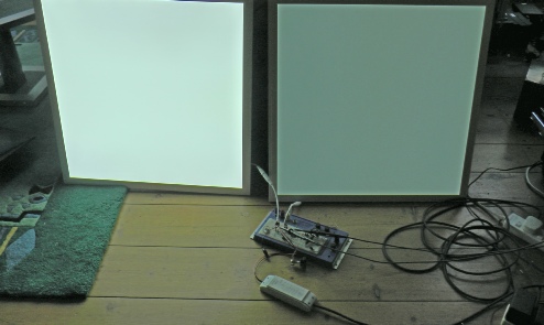
Left, shows two panels with differential brightness being driven by the bread boarded circuit.