


Under Construction
LED panels 2
Construction
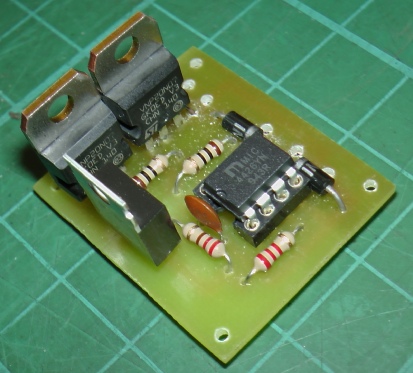
The picture on the left shows the pcb for the circuit described on the previous page. Testing shows that, as expected, no heat sinks are required.
I had intended to solder the various connections directly to the pcb but, on reflection, I decided to use screw terminals so that I could easily remove the unit for testing, modification etc. Obviously, it would have been possible to carry out the design with the terminals directly on the pcb had I thought of this earlier! As it is I will probably mount the terminals on strip board (“Veroboard”). (Also, I could have designed the pcb so that the potentiometer could have been mounted directly. I can’t quite remember why I didn’t!)
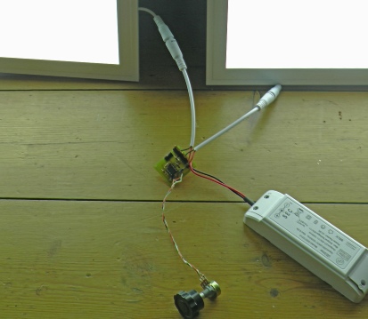
This picture shows the circuit being tested and the panels balanced for equal brightness using a temporary potentiometer.
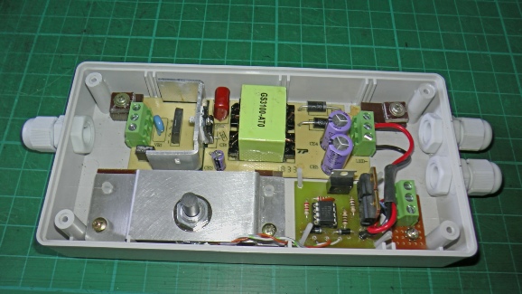
The completed unit, left. The box is a Hammond 1599 E (from Rapid Electronics) which is a good size for all sorts of projects.
The original panel controller had soldered on leads but, conveniently, it had pads and holes suitable for standard pcb-
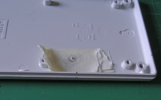
To work out where the potentiometer shaft hits the lid, I put several layers of masking tape approximately in the right position and ran a soft pencil over the end of the shaft to cover it with graphite. I the put the lid in position on the box and rocked it about to leave a mark on the masking tape. I then marked in the position of the centre by eye.
Installation
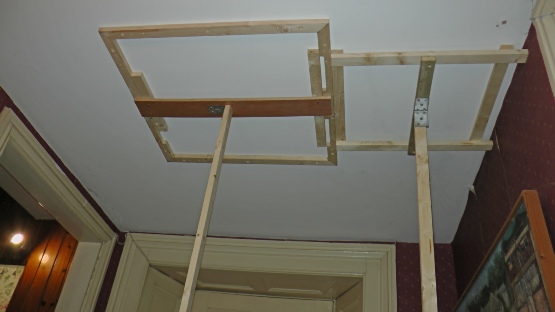
I now had the problem of fitting the units to the ceiling. I decided to frame the panels within a batten frame plugged to the ceiling and holding them in place with a frame with an ogee moulding (slightly cut down door architrave from B&Q). To get the power to the panels, I made a moulding from two pieces of architrave with a channel for the cable and fitted this to the side of the panel frame with another dummy on the other side for symmetry. The cable was then taken round the edge of the ceiling behind foam coving from Screwfix. I took the cable down an existing pilaster through the box for the existing light switch which I replaced with a double unit. You can’t, of course, derive power from an existing light switch so I took a supply from a fused spur hooked up to a nearby socket. I hope this complies with regs! I worry that in the future someone may think the switch is completely isolated when the lighting circuit is off. But then I worry about a lot of things and, for now, life goes on!
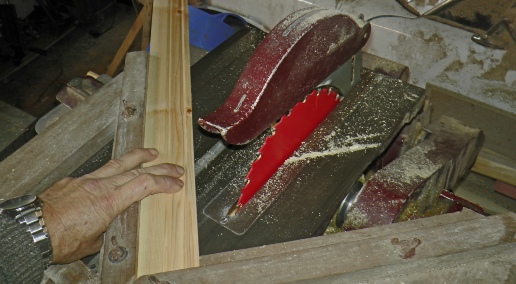
Cutting mitres on moulding for frames to hold panels
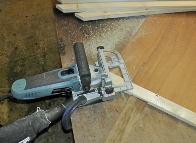
Using a biscuit cutter to reinforce the mitres
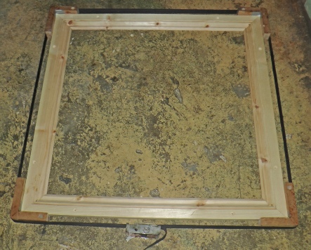
Frame glued up and clamped using an old Stanley tape clamp.
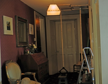
Hopefully, the panels will relieve the Stygian gloom of our windowless hall.
The prop on the left is holding up the batten frame ready to be screwed and glued to the ceiling. The prop on the right is a guide to keep the frame square with the ceiling and the right distance from the wall.
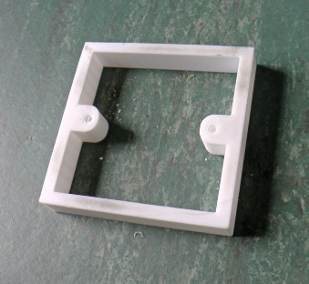
This piece was needed to space the wall switch away from the wall so the new wiring would fit. Another use for the 3D printer! (What did I do without it!)
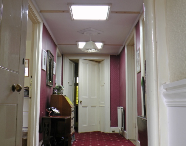
Much more daylighty! (Now we just need to do the wallpaper, paintwork etc. etc!)