


Under Construction
The development of the hardware and software in this project has had some problems! One involves getting the Feather microprocessor to detect the presence of the WiFi module following the uploading of a new sketch. After uploading my sketch, WiFi.status() returns WL_NO_SHIELD. However, if the USB lead is removed, the LiPoly disconnected then the USB lead is replaced, the WiFi Shield is detected and the connection to the network can take place. Then everything works as it should until I try to upload again. This was the case with a Raspberry Pi 3 and a Raspberry Pi B+ but not it the Feather were programmed from a PC. On the face of it, a problem with the Raspberry Pi. I considered (and breadboarded) adding an electronic switch into the USB +5 volt power connection (using the MIC4422YN) but then I discovered a program called hub-
#!/bin/bash
sudo ./hub-
sleep 1
sudo ./hub-
Use nano to create the script, save it under a suitable name like usb_onoff.sh. Then make it executable:
sudo chmod +x ./usb_onoff.sh
One odd thing is that although this worked fine with the Pi3 B+ it didn't work on the Pi3 for some reason. (By the way, it doesn't seem possible to control the USB ports individually, they are all on or all off.)
This reset does not work if the LiPoly battery is plugged into the Feather so I had to arrange a separate charger (from Sparkfun). In this new arrangement, I no longer needed a switch to isolate the battery so I deleted it.
This power-
The second problem involved the power supply I had used. I noticed there could be a problem when the Pi3 B+ would not boot up when powered via a pin from this power supply. Strangely, the Pi3 would boot up every time. It does turn out that the Pi3 B+ use a fair amount more power than the Pi3 but I don't think simple brown outs were the problem. I looked at the power supply output on my BitScope and was rather surprised to see some voltage spikes of about 0.5 volts superimposed on the nominal 5 volts output. These may be the problem. I decided to replace the supply with one prised out of an “official” RPi power supply and was amazed by the difference in size (and apparent complexity – although this does not necessarily mean a lot) between the official supply and the original eBay purchase. The eBay supply was rated at 2 amps and the official supply at 2.5 amps but the difference in beefiness between the two was more than half an amp! I just can't think why I didn't notice that the supply was so weedy as I have seen quite a few in my time. Perhaps it's the varifocal lenses in the glasses! (To be fair, a 2.5 amp supply has been recommended for the RPi for some time. It's nearly always a mistake to be a cheapskate!)
I should add that I have had some very good components from eBay. It’s not all bad by any means!
Development and mods
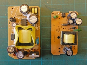
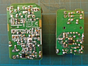
These are the power supplies discussed in the text below. In each picture the “official” Rpi power supply is on the left and the eBay special on the right. Spot the difference! Output waveforms are shown later.
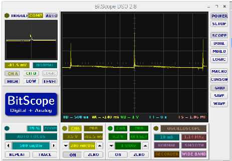
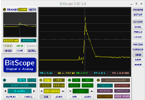

Above are traces showing the pulses superimposed on the output of the eBay power supply. They seem to occur about every 2.25 mSec. The right hand pic shows a pulse in more detail. The lower pic shows the worst I could get out of the “official” power supply. (These were outputs on no load and do not take into consideration any noise or other artefacts introduced by the BitScope itself.)
Below is the upgraded unit. The main change is the presence of the Sparkfun battery charger. The components on Veroboard plugged into the top of the Feather are decoupling capacitors which I threw in when I was concerned by the odd crash of the Raspberry Pi. I now believe these to be caused by the spikes produced by the power supply.
I have also linked seven of the unused input/output pins on the mcp2013 with seven unused GPIO pins on the Rapberry Pi. I was slightly concerned about these connections as accidentally programming both ports as outputs and having one high and the other low might cause a blowout. As noted before, I had previously included transistor buffers which made such contentions impossible. So far, I have got away with it. The p[ins may have protection built in. So now I have possible communication between the Pi and the Feather by means of the serial/usb connection, these direct connections via the mcp2013 port expander and UDP via the WiFi.
The third problem involved the Feather reset pin. As noted above, I linked one of the RPi's GPIO pins to the Feather reset pin via a transistor buffer so that the Pi could reset the Feather should it hang. I'm sure I have done a similar thing with an Arduino Uno where a hardware watchdog timer resets the processor if required. I just connected the collector of the transistor buffer to the reset pin as I assumed there was an internal resistor linked to (in the Uno case) +5 volts. In the case of the Feather, however, the impedance of the reset pin would seem to be very high as the Feather kept on resetting itself. A 1k resistor between reset and 3.3 volts improved matters but the Feather still reset on a very regular basis. I eventually reduced the value to 68 ohms. Most of the time this was stable but, from time to time, the Feather would still reset itself. Eventually I disconnected the reset from the RPi and the problem went away.
Perhaps the RPi GPIO pin is generating some positive spikes which trigger the reset but I can't think why. As far as I know pin 27 is not committed to any other function than being a GPIO. If they happen, I imagine detecting them would be difficult with the equipment at my disposal. Anyway, as noted above, the problem has gone away. Anyway, resetting the Feather in this way seemed to leave it in a messed up state and not properly reset.
Hardware completion (for now!)
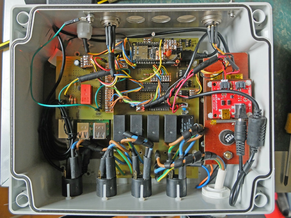
Sparkfun battery charger.
Link between the mcp3013 and the Pi.


Talking about WiFi, I have had a number of connection problems between the Feather and the WiFi. With the WiFi booster/access point mentioned elsewhere, I was sure I had a strong signal in the vicinity of the Feather (my phone, tablet etc described the signal as strong and the Pi registered three out of four bars. However, the connection kept dropping out and the software on the Feather often registered only -
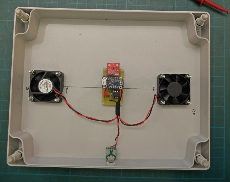
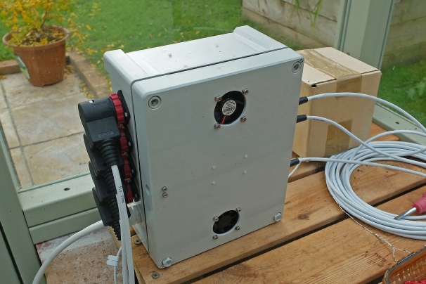
Cooling
During the long hot summer, the temperature in the greenhouse control unit reached a rather high temperature. Given that both the Raspberry Pi and the Feather were subject to crashing for no apparent reason, I began to suspect that the temperature might have something to do with it. So I devised an arrangement of two small fans in the lid, one blowing, the other sucking, to cool things down. The arrangement was thermostatically controlled using a slight modification to the arrangement I had used in my TR7 cooling system! This involved a TMP102 sensor, an Adafruit Trinket microprocessor and a MIC4221 driver for the fans, bits and pieces I already had lying around. (Later, I thought more about the crashes and it occurred to me that many happened at night when it was cooler. Also the crashes seemed to stop for no reason I could understand when I made some slight software changes. Nevertheless, I went ahead with the fans!)
Micro USB socket for power.
Adafruit Trinket
MIC4221
TMP102 sensor


1½ inch, 5 volt fans, bottom one sucks, the top blows.

The picture left shows the main components. I bought the tiny fans a few years ago for an electronic humidor project which never happened. I decided that given the concerns I had about the capacity of the main power supply (see above) I would use an independent plug in 5 volt supply for the fans.
There are continuing problems with this set up. Some have been mentioned above on this page. I touch on the case of some random crashes below.
Some problems seem solvable but the problem of the recognition of the WiFi module on the Feather won’t seem to go away.
I have considered abandoning Wifi on the Feather (there is a non-
I am resigned to be having to reset the Feather manually every time I reload the sketch.
Finally, in the light of occasional crashes, I decided to install a hardware watchdog to reset the whole shooting match if necessary. This is very similar to the watchdog I made for the Adrduino-
Details are next.
Finally?