


Under Construction
Dampness meter spin off
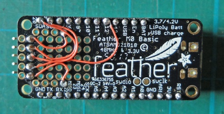
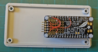
The dampness sensor I designed for the monitoring system seemed to work quite well so I decided to incorporate the circuit into a stand alone meter. I decided to use the basic version of the Feather M0 which just includes the processor in effect. There is a prototyping area where the various add ons such as the wifi unit normally sit. This version of the Feather is about £10 cheaper than versions with the various extras.
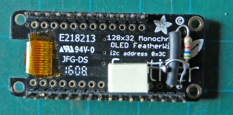
I already had an OLED Feather Wing which, as the name suggests, features a tiny OLED display. I bought this to try it out but I hadn't used it in a project up till now (other than in testing the rain gauge.)
The circuit is almost exactly as before. I used the opto-
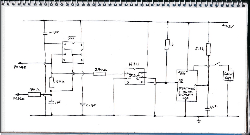
The output of the Schmitt is connected to pin 12 on the Feather. The 5.6k resistor and the 1 micro Farad capacitor are connected to the reset pin of the Feather (I notice I have forgotten to label this in the circuit above!) These are required to stop the OLED from displaying garbage on power up until the reset button is pressed. Adafruit recommend including a delay in Setup in the Feather Program to avoid this happening but that did not work for me. I wired up a 5 pin header on the prototyping area for interconnections (ground, 3.3 v, pin 12, SDA and SCL for I2C connection -
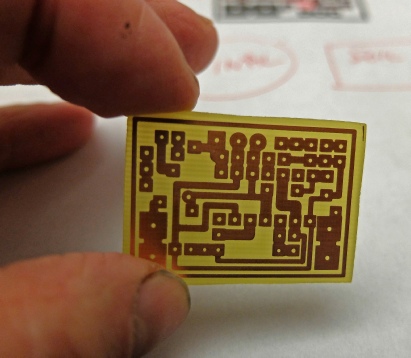
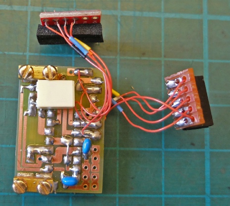
I made a pcb for the circuit, making it as compact as I could. (Sorry about the grubby fingers!) This needed to be trimmed down to just beyond the inside of the outline “track” as space is tight.
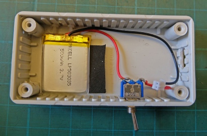
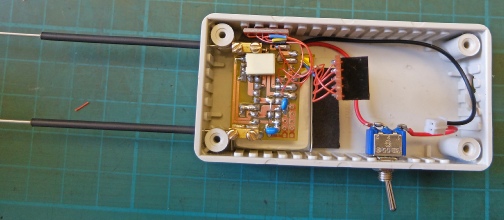
I had guessed that I could fit everything into a 100 x 50 x 25 box (Hammond 1591ASGY) by laying out all the bits on the table and taking a few measurements. However, it turned out to be a bit of a squeeze! This is the battery and the power switch. I was hoping to use a neat little momentary push button instead of the toggle switch shown here. However, I had forgotten that the battery can’t charge if it is not connected!
The black rectangle is a small piece of foam glued to the box to stop the battery sliding backwards.
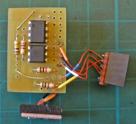
Above are the top and bottom views of the pcb. The female header which plugs into the Feather is on the right. The pcb with the small piece of foam glued to it is the TMP102 breakout board from Sparkfun. I have used this on quite a number projects now. The fine wire I have used is sold for wire wrapping and can be obtained from RS Components. I’ve put some coloured sleeves on to help with identification. These came from the wire I usually use for hookup purposes. The screw terminals were taken from 5 amp connector blocks. I filed a small flat on the underside to make soldering to the pcb easier. In order to minimise the height of the circuit, I have had to mount the capacitors on the track side of the pcb.
The Feather and the OLED are screwed to the lid of the box using 2 mm nylon nuts and bolts. The four switches on the OLED are higher than the top of the display so it is necessary to drill holes to accommodate them otherwise they will be permanently held in which will not be good, especially with the reset switch!
The pcb is held in place by the probes as in the sensors described previously. The two ICs just touch the battery and hold it in place. The TMP102 pcb locates on a couple of short M2 screws and the foam glued to it holds it in place.
Working out where to drill holes in the lid and cut the hole for the display is a bit tricky. Adafruit publish a png file which shows the layout of the OLED pcb with dimensions. This should be imported into a graphic art program (I use a very old version of Corel Draw). Draw a rectangle the size of the box lid and superimpose it on the png picture. Move the two around until the they are in the correct relative positions (the pcb needs to be as close to the end as practicable and the display should be in the middle (it is offset on the pcb). It is not clear in the png picture, in my opinion, where the cut out for the display should be. It needs to be larger than the rectangle defined by the dotted line. The picture below gives an indication of what is required.
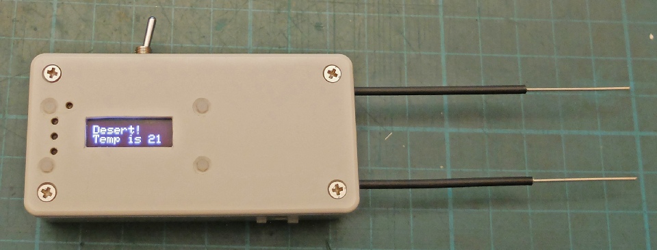
Above is the finished item. I’ve rotated the display through 180 degrees since this picture was taken making it more user friendly for right handed people. The software is described on the next page.
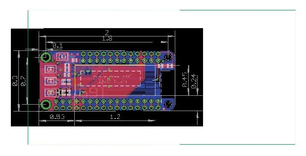


This yellow box is the cut out I used.
This green box is the outline of the lid.
Once I was satisfied with the plan, I printed it out and cut it out along the green line which is the outline of the lid. I then applied some spray mount to the back of the plan/pattern in order to stick it to the lid so the holes and the cut out could be transferred using a sharp awl or metal point. As the edge of the lid is curved it was necessary to put some pieces of wood round the lid enabling the plan/pattern to be accurately put in place.
I then used a hand drill with a 1 mm bit to drill pilot holes. This way it’t easy to feel when the drill is in the dent made by the awl and it’s harder to get the hole in the wrong place. I made a couple of large holes near the edge of the cut out and filed the hole to size.

Adafruit png