
Under Construction
Microprocessor based thermostat for cooling fan
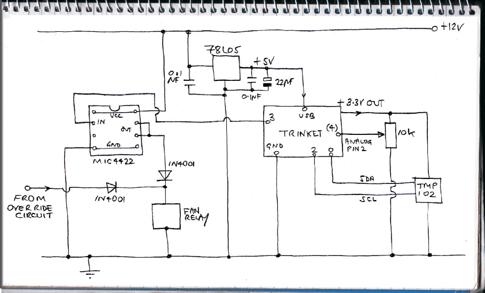
The circuit is shown above. I have used a 3.3 volt Adafruit Trinket to be compatible with the TMP102 temperature sensor which runs on 3.3 volts. I have included a separate 78L05 regulator to convert the car’s nominal 12 volts to 5 volts to spare the on-
The existing fan relay is connected “low side”, that is it has one terminal connected to ground or the chassis. Using discrete components to switch the relay, I would need an npn and a pnp bipolar (or mosfet) transistors, a few resistors and a diode to short out back emf from the relay coil. I can do a better job with one IC, the MIC4022YN.
The two diodes are needed to avoid interference between the 4022 and the over ride switch.
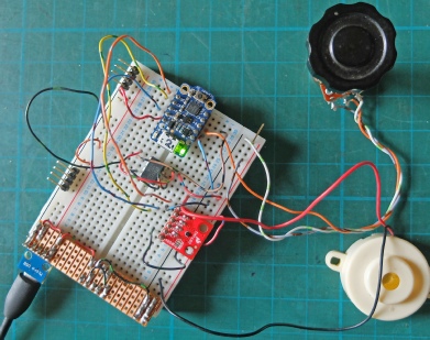
Left, the circuit is tested on a breadboard (switching a buzzer).
The mechanical thermostat I was using is intended to be fitted in the top hose of an engine where the temperature is much hotter than in the bottom hose, so the range of the thermostat is tailored to that scenario. Although the thermostat was set as low as possible, it was not low enough resulting in a head temperature higher than I wanted (95 degrees) at which point the fan operated and the pump increased the flow of water reducing the temperature (to about 80) at which point the temperature cycled back up again. I decided to try an electronic solution using a TMP102 sensor. The electronic thermostat could be set to trigger at any temperature I wanted. The idea was to clamp the sensor (on a Sparfun breakout board as used on a number of my other projects) against the side of the engine’s bottom hose. Sadly that didn’t work very well. The rubber of the hose slowed the flow of heat to the sensor resulting in too much backlash in the switching of the fan. It would be slow to come on so the temperature of the water overshot the desired value. Once the fan was on, it would be too slow to switch off. The result was the engine temperature would swing from too hot to too cool.
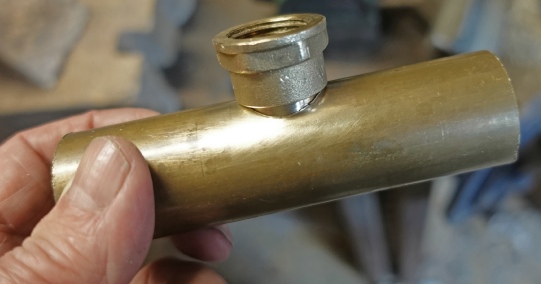
Instead, I brazed a tab to the side of a brass tube and, with suitable water proofing arrangements, screwed the Sparkfun TMP103 to the tab. This worked much better with fan running for, typically about thirty seconds before turning off and the engine temperature showing much more stability.
Circuit diagram
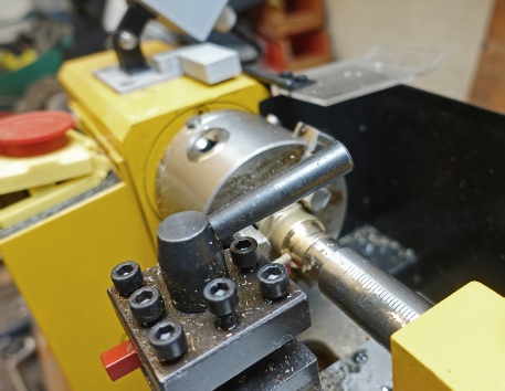
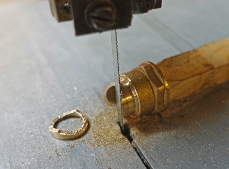
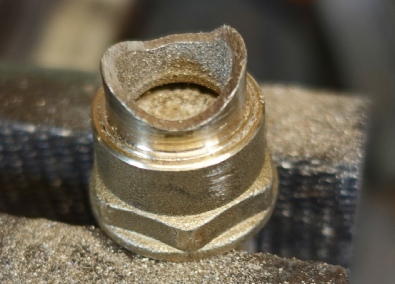

I also decided to put a drain tap in the system as I am tired of water flooding out unpredictably when you drain by taking off a hose. I found an old plumbing drain tap with a ½ inch BSP screw and a ½ to 15mm compression tap union. The first task was to turn the thread off the compression joint end of the union (below left). Then I cut a curve in the end with a band saw to reduce the obstruction to flow when the union was fitted into the main pipe work (below right).
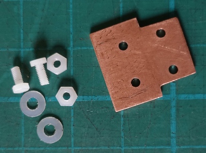
The hardware
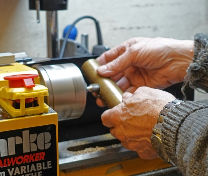
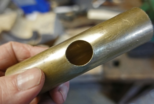
Next I took a piece of 1¼ inch brass tube and made a hole in it so that the tap union would fit as tightly as possible. The brazing or silver soldering processes are not gap filling so the fit needs to be as good. I started by drilling a small hole and then enlarging it with rotary files, testing the fit every few seconds (below left). If the union hal been filed down to be a reasonable fit over the tube, you can mark the hole required with a fine marker. Just remember this will be slightly larger than the required hole. You can attach a piece of abrasive paper to a dowel just smaller than the hole required, put the dowel in the lathe chuck and use that for the final adjustment of the hole. Push one end of the paper into a saw cut in the dowel. The other end does not need to be fixed down as long as you wind it the right way round the dowel. If it’s the wrong way round it will be apparent immediately you try to use it!
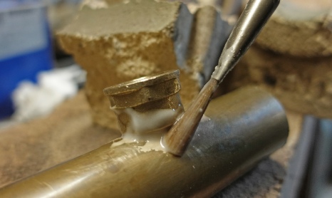
Below left: final filing of the union to shape. Below right: it fits in the hole, hopefully, with no significant gaps.
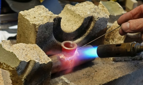
Below left: brush some suitable flux mixed with water round the joint. Below right: put the work on some fireclay (these are bits of brick from an old storage heater) and heat everything up to red heat with a gas torch. Dip the brazing rod (from B&Q and as low temperature as possible) in the flux and apply it to the joint. Avoid directly heating the rod with the flame -
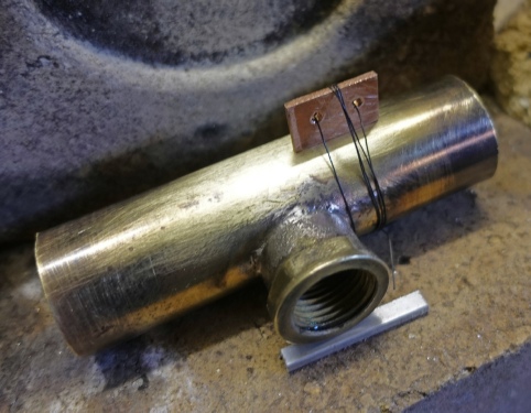
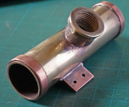
You can plunge the metal into water when the brazing is complete in order to cool it. The thermal shock helps to displace the flux residue which otherwise, needs to be removed with abrasive paper etc. Below left: I then held the tab in place with soft iron binding wire which is sold for this purpose. More brazing followed. Finally, I soft soldered a couple rings to the tube to prevent the cooling hoses from sliding odd.
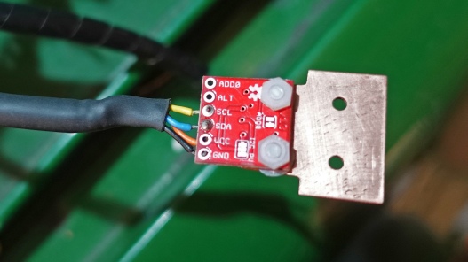
Below left: the copper tab to which the Sparkfun TMP102 is screwed which is in turn bolted to the tab brazed onto the pipe. Four connections are needed to the TMP102: ground, +3.3 volts, SDA and SCL. I used M2.5 nylon nuts and screws to secure the module to the tab. A nylon washer is just thick enough to have the actual tiny TMP102 chip almost resting on the copper without it contacting any of the soldering on the module. A smear of heat transfer grease on the tab helps rapid heat transfer and a fast response from the chip.
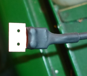
Below left: some heat shrink tubing and some silicon seal, hopefully, waterproof the sensor.
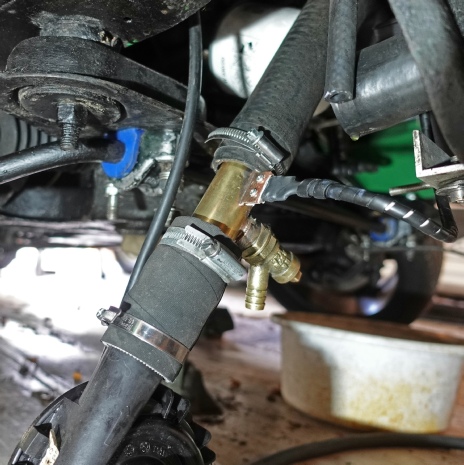
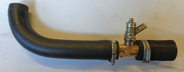
Below right: the complete unit with the drain tap and hoses ready for installation.
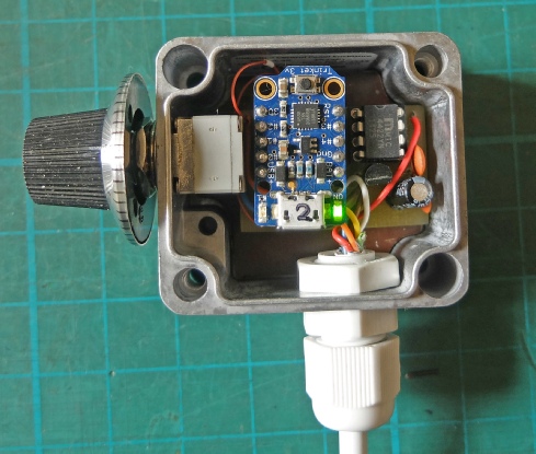
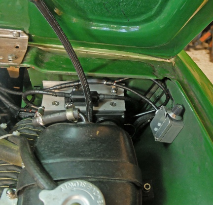
Below left: I designed a small pcb for the circuit and it (just) fitted in a small die-
Right: the lower hose has been attached to the Davies-
A suitable piece of hose will be fitted to the drain to conduct water past the undertray.
Radiator bottom hose.
Pump.


Electronics
Pot to adjust temperature.
Trinket
MIC4422