

 Home
Home


Under construction
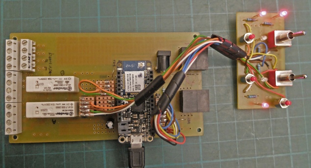
Adafruit Feather IOT controller construction and testing
Mains connection by screw terminals
I2C connection by RJ45 connectors
Power LED
“Advance” LED
Circuit “A” override
Circuit “A” on LED
Circuit “A” advance button
Circuit “B” override
Circuit “B” on LED
Circuit “B” advance button
Reset button
“Running” LED


During assembly of the circuit, I noticed several mistakes which required track cutting and bridging with wires. This is annoying because 1). it doesn’t look nice and 2). It reinforces my long-
I wrote a simple sketch to test the switches and LEDs and to show that I had assigned them to the right pins etc.
#include <Adafruit_WINC1500.h>
#define WINC_CS 8 // chip select for wifi
#define WINC_IRQ 7 // irq for wifi
#define WINC_RST 4 // reset pin for wifi -
#define WINC_EN 2 // or, tie EN to VCC and comment this out -
Adafruit_WINC1500 WiFi(WINC_CS, WINC_IRQ, WINC_RST);
void setup() {
pinMode(15, OUTPUT); // advance led
pinMode(13, OUTPUT); // rly A
pinMode(12, OUTPUT); //rly B
digitalWrite(15, LOW);
digitalWrite(13, LOW);
digitalWrite(12, LOW);
pinMode(17, OUTPUT); // on led A
pinMode(19, OUTPUT); //on led B
digitalWrite(17, LOW);
digitalWrite(19, LOW);
pinMode(11, INPUT_PULLUP); // adv B
pinMode(9, INPUT_PULLUP); // adv A
pinMode(16, OUTPUT); // "running" LED
digitalWrite(16, LOW);
Serial.begin(9600);
}
void loop() {
int A = analogRead(0);
int B = analogRead(4);
Serial.print("A = ");
Serial.println(A);
Serial.print("B = ");
Serial.println(B);
if(digitalRead(9) == LOW){ //advance A
digitalWrite(17, HIGH);
digitalWrite(13, HIGH); //relay A
}
else{
digitalWrite(17, LOW);
digitalWrite(13, LOW);
}
if(digitalRead(11) == LOW){ //advance B
digitalWrite(19, HIGH);
digitalWrite(12, HIGH); //relay B
}
else{
digitalWrite(19, LOW);
digitalWrite(12, LOW);
}
delay(980);
digitalWrite(16, HIGH); //comms led
digitalWrite(15, LOW); //advance led
delay(20);
digitalWrite(16, LOW); //comms led
digitalWrite(15, HIGH); //advance led
}
This prints the analogue values used to detect the position of the override switch and turns on the LEDs and relays in response to the buttons and swiches etc.
This resulted in correction to the pin designations I had thought were correct and also led to some more circuit correction, unfortuately.
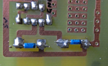
I also noted that when the relays turned off, the processor reset. It turns out that because the driver IC I am using to trigger the relays has built in protection diodes, I hadn’t bothered to put individual diodes across the relay coils to suppress the reverse voltage generated by the collapse of the magnetic field in the coil when power is removed. I forgot that the relay coils were also operated by the override switches independent of the driver IC, so when the switch was operated, a negative voltage was impressed on the power supply and the processor reset itself.
On the precious controller design, I had used individual transistors to drive the relays. These need diodes for protection so the above problem had not previously arisen.
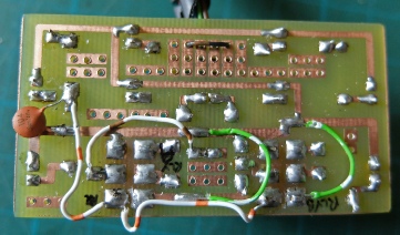
Wiring mess up!
Added diodes
Next: case construction.