IOT Feather controller
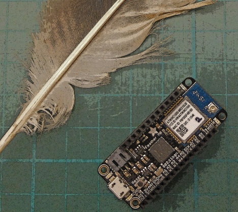
The Adafruit Feather is a microcontroller board which is programmed from the Arduino IDE but which offers a great deal more capability than, say, the Uno, in a much smaller package. This Feather MO WiFi has, as the name suggests, built in WiFi and there are a number of plug in boards, or “wings” which can extend its powers. The wing I am using is the Adalogger which has a real time clock with battery backup and an SD card slot.
This package is tiny compared to a Uno arrangement but when you add on the mains voltage relays, mains rated sockets etc. etc. the whole unit has limits as to how small it can be made.
A big advantage of the Feather over the Uno is that it has a very much bigger memory. With my last timer/controller project I found that I was very near the maximum memory usage limit for reliable operation. I did get very occasional crashes and had to install a hardware watchdog timer to reset the Uno should it hang up. I am hoping this will not be necessary with the Feather. Time will tell. Of course the Feather has not been around as long as the Uno so all the bugs may not have been eliminated…

 Home
Home


Under construction
My new project is another IOT type controller/timer which I want to build into my heating system to control radiators in the living rooms with motorised valves when these rooms are not in use. This time I am using an alternative to an Arduino.
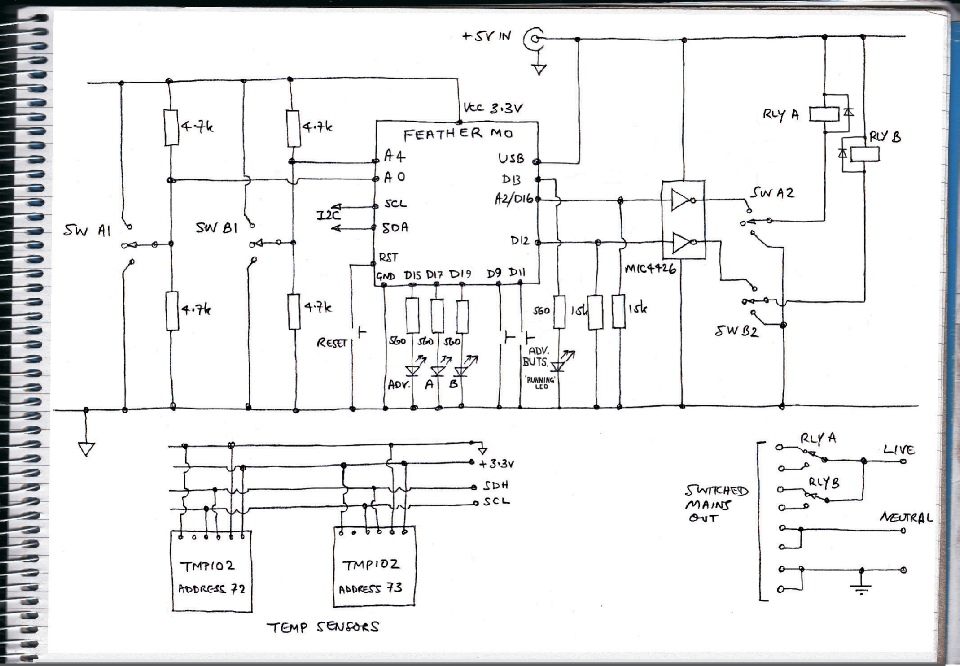
Circuit diagram
Control system functions
The system will control two independent mains circuits through 10 amp relays with single pole changeover contacts which may be useful in turning valves on and off, for example. Like my previous controller, I am avoiding alpha-
The switches marked A and B are two pole changeover with centre off.
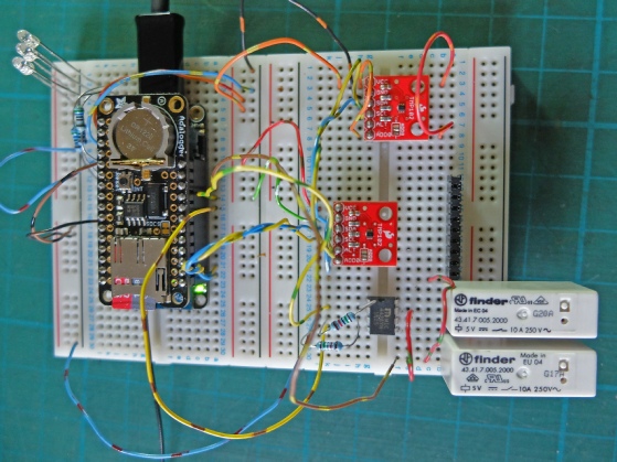
I built most of the important parts of the circuit on a breadboard to test out the software which was adapted from the previous Arduino-
Having so much extra memory, however, was a delight.
The new software can be found here.
The Adafruit Feather MO is shown above. It’s quite small (the squares are about ½ inch across). The view below (on the breadboard) shows the feather with the Adalogger Wing plugged in (this contains the real time clock and the SD slot).
I then began to design the details of the actual unit. This involves laying out the main components on the table and trying to get them into the most efficient positions with regard to compact packaging and electrical connections. In spite of the fact that the Feather is a fraction of the size of the Arduino, a lot of space is taken up by mains relays, connectors and mains rated plugs and sockets. So in the end I used the same sized box as I had used for the previous version (Hammond 191 x 110 x 61 mm -
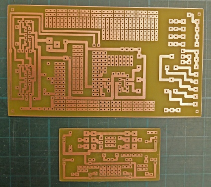
Next, I designed two PCBs, one for the main circuit and one for the switches and LEDs which would be attached to the front panel. As is my custom, I included plenty of unassigned pads to allow for additions and the correction of mistakes.
Although the fact that I could adapt parts of the PCB design from my previous controller made the new design to some extent quicker, major differences in pin numbering and designation (and function) between the Arduino and the Feather left plenty of room for confusion and errors (especially as I tend to do this sort of thing late at night!)
The software conversion also gave me similar problems. With hindsight, it might have been easier to have started completely from scratch!
Construction details are next.