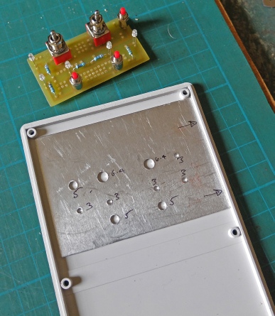
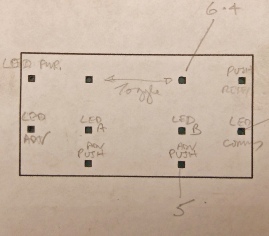
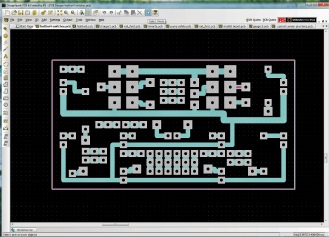
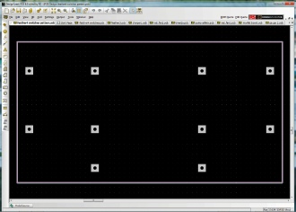
To cut out the holes in the front panel in the right places, I modified the PCB design with a pad in the centre of each switch and LED, printed this out and centre-punched through into a thin sheet of aluminium which I drilled and then fitted the switch PCB in place to confirm that everything was in order.
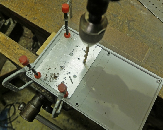
I then clamped the aluminium pattern to the front panel and drilled though the holes.
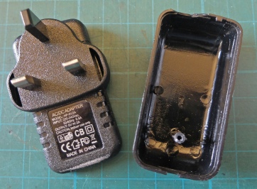
Discarded case of power supply.
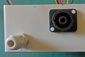
Touch-proof 4-way mains connector.
Cable gland for mains input.
5 volt power supply extracted from case. Needs an insulated cover to prevent it being touched.
Touch-proof 4-way mains connector with extra insulation provided by sections of bicycle tyre inner tube.
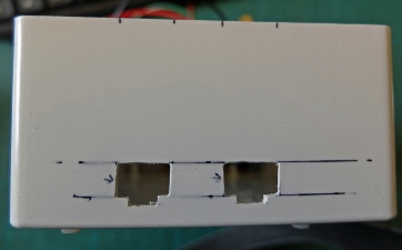
Cut outs for the RJ45 connectors used for I2C.
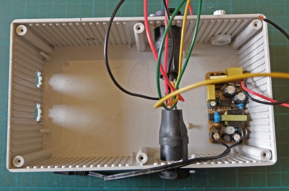
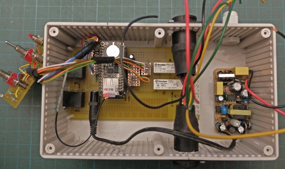
Above right, the PCB and other components are trial-fitted into the case. I can see I have left myself short on space for getting the eight wires from the mains sockets, the three wires from the mains input and the two wires to the power supply all into the screw terminals at the right of the PCB. I should have designed the PCB with the relays below the Feather and moved the screw terminals about 25 mm to the left. Ah well! future lives!
Hopefully, with a bit of a struggle I can get all the wires in!

 Home
Home