Julian Rogers Home Home New temperature sensor for Feather controller Feather IOT controller case construction

Under construction

During the testing process one or two issues cropped up. When the processor was reset, the relays clicked on and off. My first thought was that I had forgotten the pull-down resistors on the output pins of the Feather. On start-up the pins are initially in a high impedance state which is like saying that anything which is connected to these pins will act like it's disconnected. So if the thing being driven by the output pin is high impedance, it will take on any voltage up to the supply voltage according to random static charges etc. The pull-down resistor shorts out these charges and makes sure the input is zero volts or “off”. It turned out I had used pull-down resistors (7.2k). Perhaps this was not low enough. So I tried 1.2k. The relays still clicked. However when I bread-boarded the Feather, driver and one relay, it didn't click.


I then took a wrong turn which wasted a lot of time! I felt convinced that all output pins on the Feather went high during reset. I noticed that the red LED on the Feather flashes during reset. However, on the bread-boarded circuit it flashed for a much shorter time than when the Feather was installed on the PCB. So I thought that perhaps the high on the output pins was too brief to trip the relay. But why should the reset process vary in length. It must be something to do with the loading of data into RAM,  initialising variables etc.


All this conjecturing proved to be beside the point when I finally realised I had connected one of the relays to pin 13, which has the on-board red LED connected to it. (On the bread board I had used pin 12). What a silly billy! This resulted in more track cutting and soldering of wires to re-route the circuit. I don't think I have ever designed a PCB that hasn't required correction. Ah well!


Feather controller testing and completion

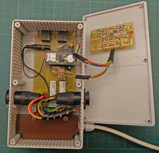
Too many PCB alterations!

Real time clock battery.

SD card to store on/off times etc.

Adafruit Adalogger with Feather underneath.

Sockets for I2C.

Relays

Power supply for Feather under this cover.

WiFi antenna

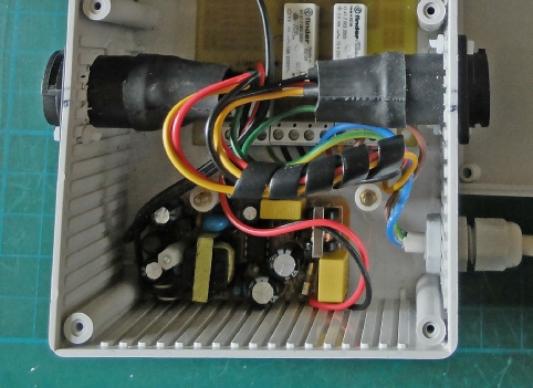
2 amp, 5 volt Power supply removed from its original case.

Next I construct an I2C temperature sensor.

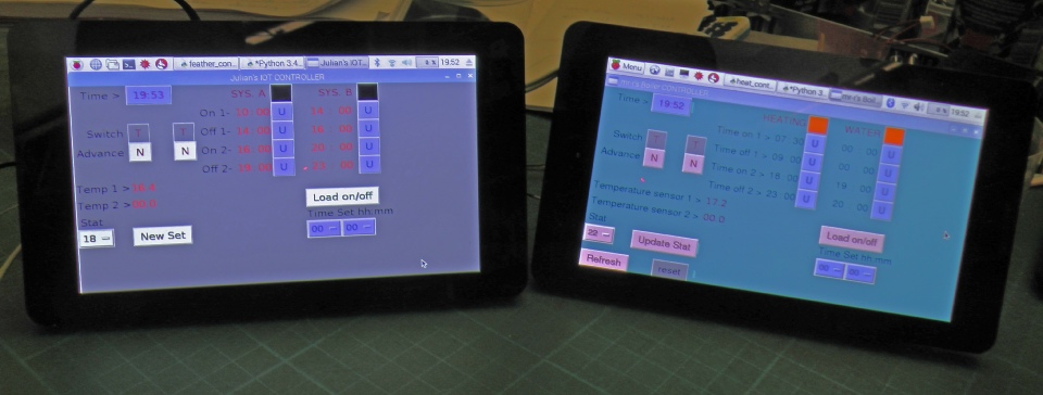
The Raspberry Pi on the left is running a cleaned up version of my original Python software which is supervising the new controller. I’m hoping to extend this so it can be switched between the old and the new controllers.