 Home
Home


Window control circuit construction
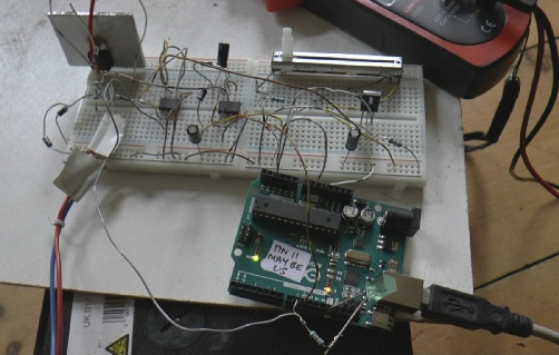
Breadboard circuit to test operation of the window motor speed control. Initially, I was using an Arduino as the microcontroller. (One pin is duff due to my careless connections, probably, but everything else works ok.)
From a programming point of view, the Trinket and Arduino are very similar (apart from the different numbers of pins etc.)
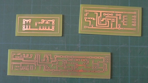
The circuit boards were designed on free Design Spark software, printed out on inkjet film from Rapid Electronics. I put two printouts together to ensure maximum opacity. Then 2 ½ minutes exposure on photo-
On completion of the etching, remove the remaining resist with hot developer or do as I do and remove it with fine wire wool (wet). It is possible to deposit tin on the copper. This makes it look more professional and should make soldering easier and reduce the likelihood of corrosion in the future. However, I never bother.
I then drill the holes with a 1mm drill bit in a PCB drill stand. I wear a pair of head magnifiers and try to aim the drill carefully. Always make sure you have a sharp drill bit. Anything blunt is slow, raises a burr round the hole and can wander from where you want the hole to be. I usually enlarge holes where required with a drill bit in a pin vice.
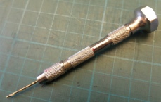
Pin vice and drill bit
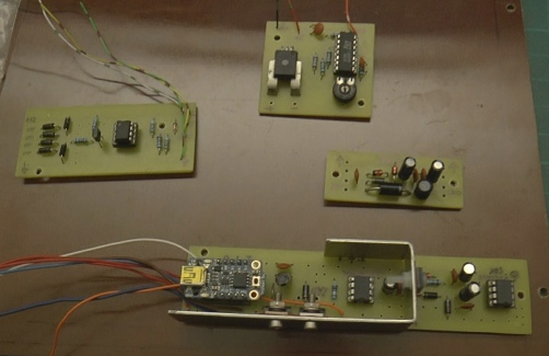
Current sensing
Power filtering
Input from switches
Over voltage generator
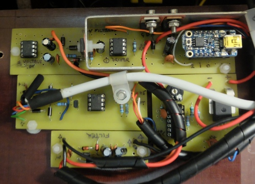
Mosfet driver
driver
Mosfet
5v regulator
Trinket


ACS756


First some testing
Three of the PCBs for the circuit.
Making the PCBs
The circuit worked satisfactorily and the windows operated at a more sedate pace and stopped when they reached the end of their travel (or hit an obstruction). The circuit could be simplified somewhat and certainly made a lot more compact. I’ll leave that for future lives, though! I am, however, thinking of using a similar circuit to match the speeds of the two headlamp motors which are annoyingly slightly out of sync. Or perhaps just a high wattage resistor would do? Probably not, as “Complicate-
Conclusion