


Under Construction
Watering system
This is a relatively simple system to water items in my greenhouse using a soaker hose (or seep hose), sprays and drips. The idea is to turn on valves supplying the water under program control.
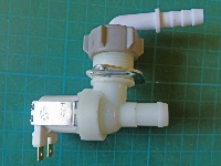
The valve shown left is a generic washing machine valve available very cheaply from eBay. It turns on when supplied with 230 volts AC.
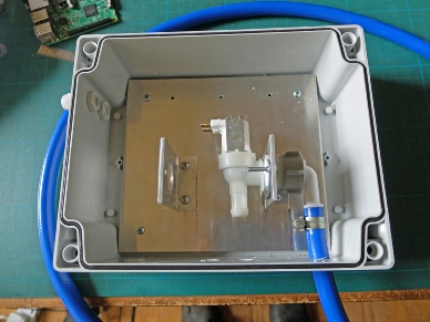
I have fitted the valve into a Fibox from Rapid Electronics. The blue inlet hose is a washing machine hose from Screwfix. I had to cut off the crimp sealing the hose to the screw-
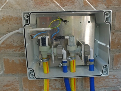
The picture on the left shows two valves in the box wired up with separate cables fitted with spade connectors. The yellow hoses are the outlets which are connected to the irrigation hoses. At the other end of the cables are fitted Cliffcon plugs which marry up with sockets on my control box.
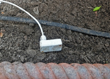
This is a section of soaker hose in a bed where we are growing tomatoes. The bed is about 2 feet wide and the hose loops back on itself at the end of the bed back to the start. Also visible is my experimental soil dampness sensor.
The hose needs to be blocked at the end (obviously!) I run it at mains pressure.
However, the micro-
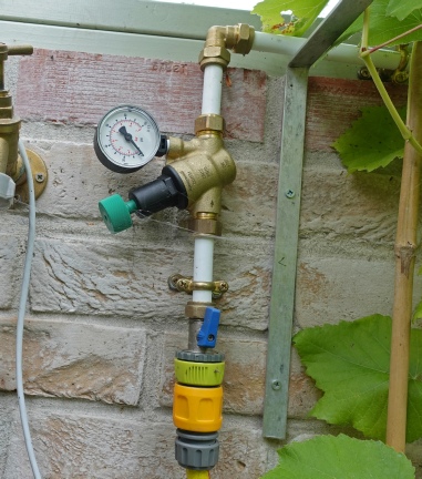
I am using a Honeywell pressure reducer (PRV) from Screwfix (7978J I think). The inlet (at the bottom) comes from the yellow hose (from the electromagnetic valve) to a washing machine isolation valve (Screwfix 51231). The green plastic item is a Hozelock type male union screwed onto the ¾ BSP union on the valve. The water is flowing the reverse of what is normal but it doesn’t seem to be a problem.
I am using 15mm plastic pipe and brass compression joints. I could have use push-
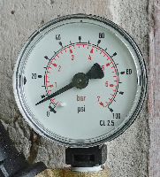
Right shows just how low the pressure needs to be if the micro irrigation system is not to blow apart and/or flood the whole joint!
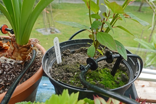
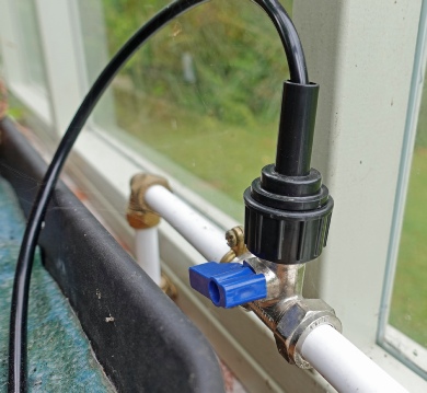
Above is the drip system in operation. All the pipe (about 5mm internal), joints, drippers etc. are available cheaply on Ebay. The connector to another washing machine valve (left) contains a mesh filter and a restrictor. Even so, you can see that the tap needs to be barely on to avoid a flow rate which is too high. The discs on the pipe seen in the right picture release water as drips.
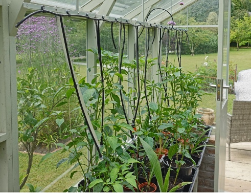
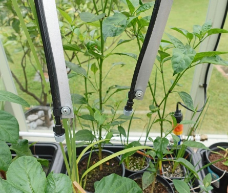
The spray system is shown above. The system is supported by an aluminium bar, ½ x 1/8 inch. This is suspended by more bars from the greenhouse rafters. The nozzles are held in position by thin aluminium cut from sheet. These are bolted at the top and can be angled side to side and bent front to back to point the nozzles in the appropriate direction. Again, all this kit is available on Ebay. You need more nozzles than you think as the angle of spray is not very great. The plant pots are contained in a tray with an absorbent liner. I have found that a three minute a day spray keeps the plants going but that will depend on water pressure etc.
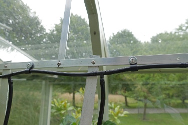
Left shows some construction details. The aluminium looks like it’s riveted together but those are 3mm screws with nyloc nuts on the rear side. The pipe clips are pop-
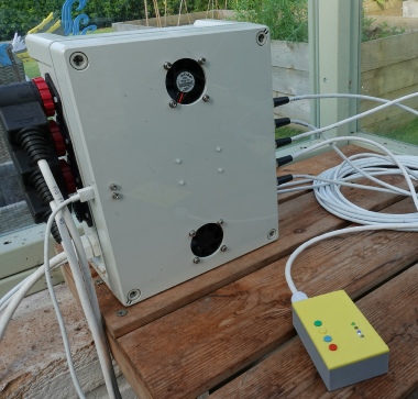
The watering system runs off the main greenhouse controller. The Feather triggers a couple of relays which turn the valves on and off. When I designed this I deliberately avoided putting any buttons or switches etc. on the panel. This was because I wanted to keep the system as simple as possible and also at that time I didn't know what controls I might need. So all the controls were by software (via a remote PC or Android tablet or even RPi).
This proved inconvenient, for example when I was in the greenhouse saw that I needed an extra burst of watering and I found myself unplugging the cables to the watering valves and plugging them directly into the mains supply which was rather stupid.
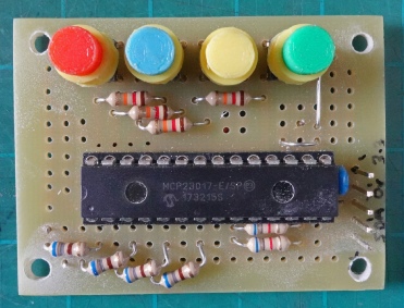
I decided to make a general purpose switch unit which could plug into the controller's I2C bus. I decided to keep it reasonably straightforward and went for four push-
Control of the system
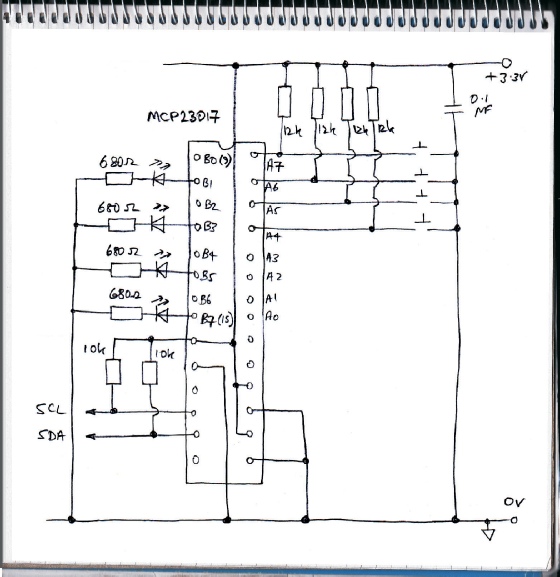
Above: the circuit diagram of the unit -
Above, top: the top view of the pcb with 3-
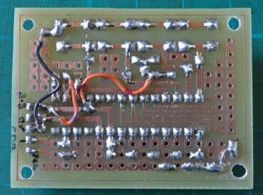
Above, bottom: the underside of the pcb.
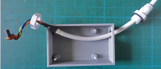
Above, left: the 3-
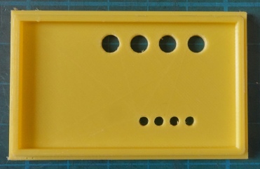
Above, right: the lid for the unit with holes for the switches and LEDs.
Left: the completed unit plugged into the greenhouse control box.