 Home
Home


TR7 gauges part 2
Having enlarged the holes in the front panel, I temporarily fitted the gauges and then went about cutting away what was needed of the rear moulding (the white bit) until I could get the gauges to fit. The part of the white moulding that had to be left was the part that supported the illumination of the warning indicators.
I had to do away with the flexible circuit which made all the connections, including to the warning lights, so I had to remake all the connections with connecting wire. I cut the original wiring loom having identified all the wires and soldered on an 18-
I used panel mounting LEDs from Maplin as they fitted the existing holes and screwed in easily. However, they were nowhere near bright enough and later I went back to the original bulb holders but fitted with much brighter LED lamps. Since I had done away with the original flexible printed circuit, I had to make new (non flexible) PCBs which suited the lamp holders. They need holes making to accommodate the bayonet type fixing of the lamp holders.
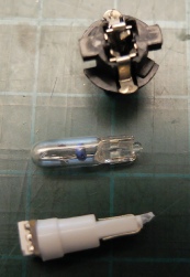
The original flexible printed circuit provided the connections to the lamp holders
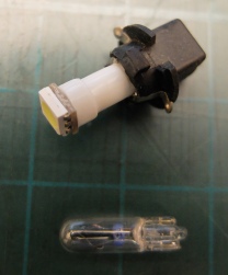
An LED lamp in the original lamp holder & an original filament lamp
Another view of the holder filament lamp and LED
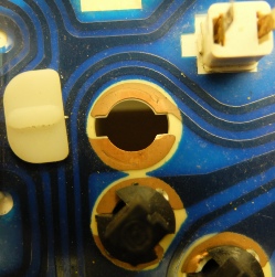
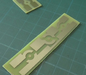
I had to make PCBs to enable the original holders to be connected up.
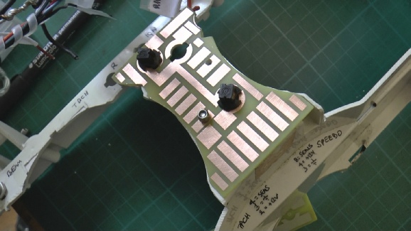
The picture on the left shows the main PCB fixed to the rear cluster moulding and also shows how the plastic has been cut away to accommodate the instruments. You can see that the hole in the PCB is the same as that in the original so that the lamp holder can twist in. The original hole has to enlarged to clear the lamp holder in its new position. The extra pads were put in so I could make soldered connections as I went along.
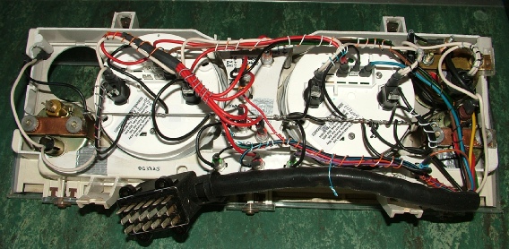
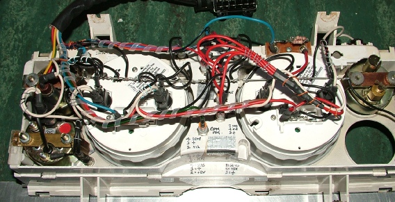
The picture below shows the whole rear of the cluster before re-
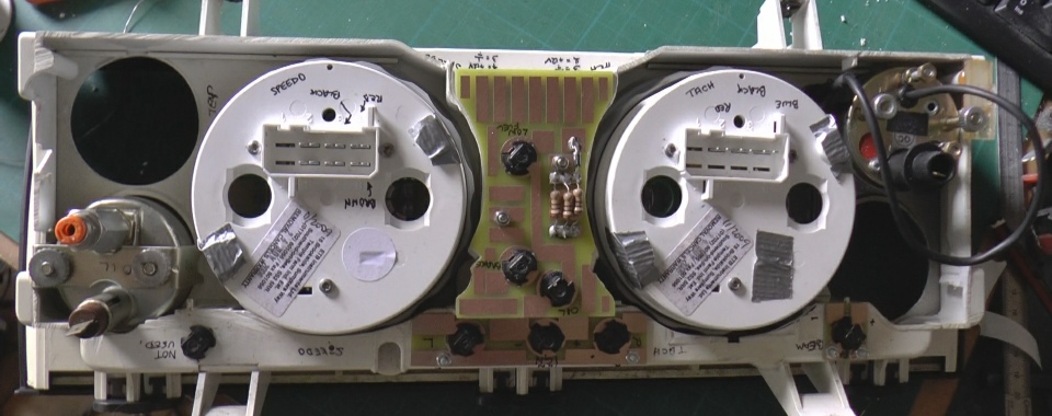
Above and below: original re-