Home
Home


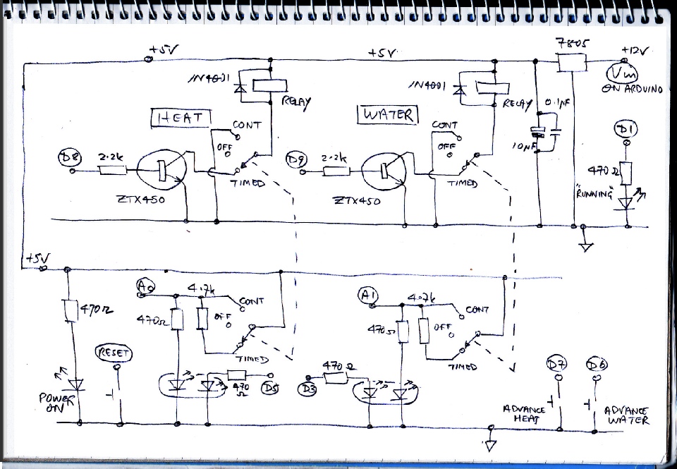
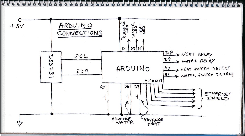
The circuit is reasonably simple. The main elements are an Arduino, an Ethernet Shield, a real time clock module (DS3231 from Ebay -
The relays are driven by a couple of ZTX450 transistors or similar 1 amp general purpose transistors.
There are two three-
The switches are 2 pole. The second pole is used to let the Arduino know what the switch positions are (largely so they can be reported back to an application running on a remote computer. I used analog input ports to do this to economise on ports used. The resistors and the LED form a potential divider whose output to the port varies with the position of the switch.
The LEDs are all tri-
There are three buttons. One is reset (connected to the Arduino reset) and two advance the heating and water programs to the next timer event. (Advance is cancelled by pressing reset.)
There are three other LEDs. One indicates power is present, one indicates the advance function is in operation and one is linked to D1 on the Arduino. This pin is used in Arduino serial comms and if it is flashing, it indicates the Arduino is operating and not “hung” (just in case!)
Central Heating Timer Circuit
Parts list (reasonably comprehensive, I hope!)
1 x Arduino Uno
1 x Arduino Ethernet Shield
1 x 8 Gb micro SD card
1 or 2 x TMP102 breakout module, Sparkfun
1 or 2 x Bi-
1 x Real time clock DS3231 (search for this on Ebay)
1 x 2032 battery (don’t trust the one the DS3231 came with!)
Some 0.1 pitch header strip
1 x ABS Hammond plastic box 191x110x61, Maplin N77BQ
1 of each Clifcon touch-
2 x Taiway DPDT centre off toggle switches, Rapid Electronics 75-
2 x 4 way Camden Boss terminal block 5mm pitch, Rapid Electronics 21-
2 x Finder PCB mount relay 5VDC 10A SPDT, Rapid electronics 51-
5 x 5mm tricolour LEDs, Rapid Electronics, 55-
3 x Push to make switches, Rapid electronics, 78-
8 x 470 0hm resistors
2 x 4.7 k Ohm resistors
2 x 2.2 k Ohm resistors
1 micro Farad electrolytic capacitor
2 x 0.1 micro Farad capacitors
2 x 1N4001 diodes
2 x ZTX450 or similar transistors
1 x 7805 1A regulator
Strip board (Vero board or similar)
RJ45 sockets (I used these for the temperature sensors but other types would suit)
1 or 2 x BS box, grey, 80 x 40 x 17 Maplin SC80B -
PCBs
Connecting wire, nuts and bolts, solder etc.
12 volt power supply
Ethernet cable
Home Plug system if needed.
Arduino and Processing software (open source).