 Home
Home


Switch panel
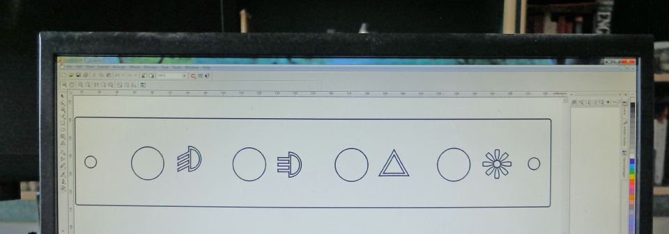
This is how I made the custom switch panel. First I used Corel Draw (but any vector graphic drawing program would do) to design the panel full size. I wanted to use symbols to identify the switches which would be backlit with LEDs so I drew those using the standard circle, line and curve tools along the lines shown below (although this is not the actual design which went missing in some hard drive!) I then cut the design out in 3mm black Perspex using a laser cutter. (I used to work in a school which had one in its technology department.) It’ so easy to do -
Design on Corel Draw
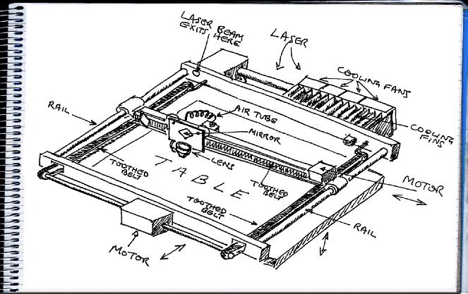
The laser cutter has two stepper motors which move a cutting head to any position over a table by means of tootherd belts just like an inkjet printer. The laser beam is bounced off a series of mirrors and focused by a lens on the cutting head onto the surface to be cut.
The laser in the machine I was using was only powerful enough to cut plastic or MDF etc. but more powerful (and very expensive) machines can cut through thick steel (or James Bond’s vitals!)
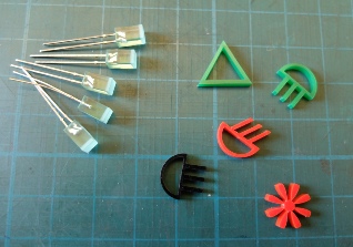
These are some of the coloured bits ready to be glued into the panel.
On the left are some rectangular LEDs (Ebay etc.) which I glue onto the back of the panel to light the symbols (see below).
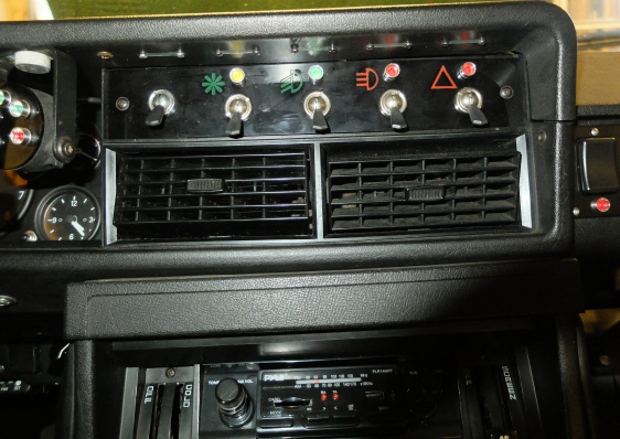
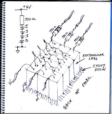
I glue rectangular LEDs over the back of the symbols connect them up in groups of four in series with a current controlling resistor for each set. Use heat shrink tubing to prevent short circuits.
Each green LED drops about 2 volts so four in series drops 8 volts. So if we want about 10mA to flow through the LED chain our resistor will have a nominal 12 – 8 = 4 volts across it so Ohm’s law says the resistor should be R = V/I = 4 / 0.01 = 400. The nearest value is 390 ohms.
If you want a brighter light, the resistor value could go down as low as 100 ohms with the resistor rated at ¼ watt.
You can chose to connect to an ignition or side light supply.