


Under Construction
Raspberry Pi case etc
A 3D-
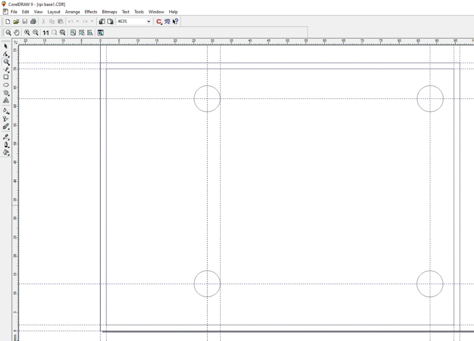
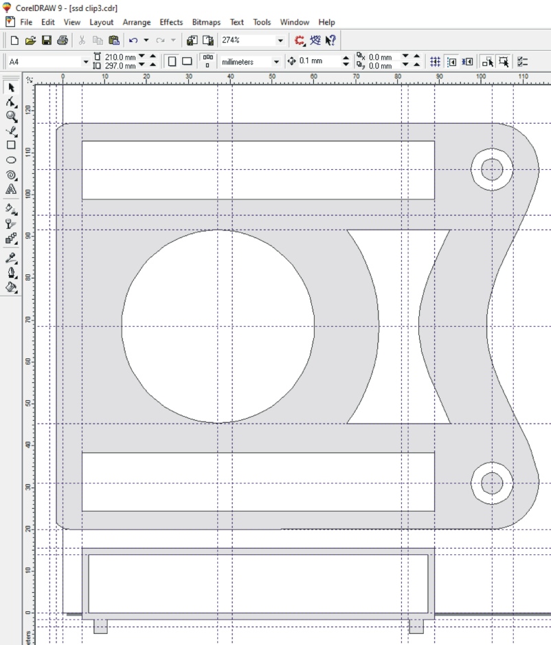
Because of my familiarity with this ancient version of the vector graphics program, CorelDRAW, I tend to start off my 3D printing projects with the sort of drawing shown below. You can set guide lines to exact dimensions and snap lines to them. You can easily draw rectangles, circles, ellipses etc or you can draw Bezier curves. You can convert circles etc into Beziers and join them to other curves as required.
I then have to go through a rather tedious process to get the 2D drawing into Design Spark Mechanical where I might add a few bits and bobs then extrude it into a 3D shape with perhaps some rounding off etc. Design Spark does not seem easy to design in and a number of features seem to require a sub to have them added. But perhaps I need to learn more about the program. All in good time, hopefully.
Anyway, I export from CorelDraw in WMF format, import in Open Office (Drawing), export in SVG format, import into FreeCAD, export in STEP format, open in Design Spark! Maybe there’s a macro to do that.
The shot of the design, below, should give an idea of the dimensions. I have found, it should be noted, that my 3D printer has a slight inaccuracy in reproducing the dimensions of the parts of a drawing and, as you would expect, this error is larger for larger objects!
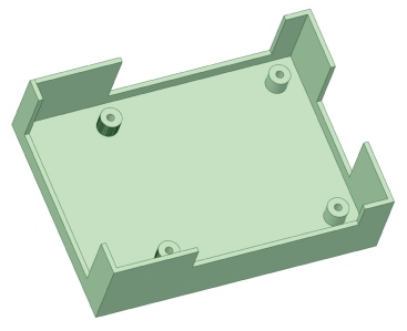
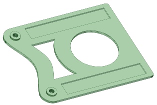
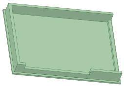
In Design Spark it looks like this after extrusion etc.
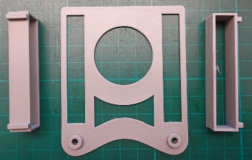
Below is the 2D design for the other bits I need for this project. I’ve shaded them in for clarity (a sort of French wine) but I don’t think they should be filled when being exported. These parts hold the USB SATA drive and allow the whole thing to fitted onto a VESA mount on the back of a monitor.
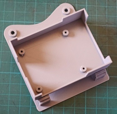
Left: this is how the bits turned out. I could have made the main part thicker and just sunk recesses into it for the two support pieces -
Anyway, I super-
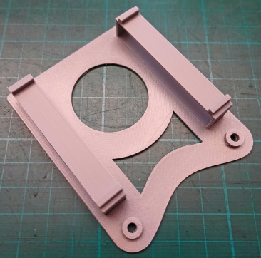
Finally, I glued the Rpi case to the supports with epoxy.
Right: supports glued in place.
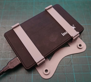
USB hard drive case slides in.
Rpi case glued on. I don’t thread the holes in the support for the Rpi. The size of the holes and slight inaccuracy in the positioning of the supports means I can just press in suitable M2.5 nylon screws.
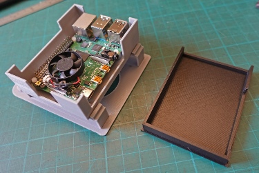
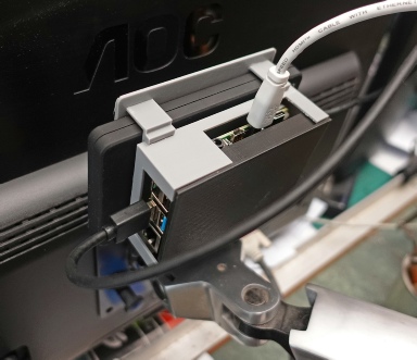
Right: Rpi in the case together with a lid. The lid is a push fit into the box so no screws needed.
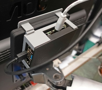
The whole thing screwed to the back of a monitor.
Right: slots filled in and thickness upped to 2.5mm which I would recommend. Other parts can stay at 1.5mm thick.
Left: the lid