


Under Construction
Rain Gauge
Years ago I worked with a professionally made “tipping bucket” rain gauge (from by the lab suppliers, Gallenkamp or possibly Griffin and George). This was to do with a system for monitoring water ingress into buildings vulnerable to dry rot which I was trying to develop -
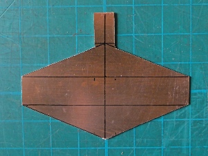
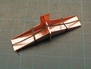
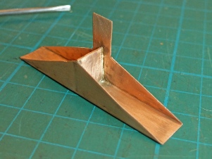
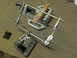
The size, geometry, centre of gravity etc of the bucket is obviously important but rather than try to do any proper deigns or calculations, I decided to work on instinct! I had some thin sheet copper so I worked with that. (I would have preferred brass as it does not soften when you get it really hot (for silver soldering). Also it doesn't soak up heat so much as copper making soldering easier. Anyway, copper it was! I cut the shape out with a band saw (it’s 75 mm long) and bent it in a vice. I made the central division with a slit to hold it in place while I soldered it and cut this bit off after. The tab was there to have a magnet attached or to break a beam for an optical switch but in the end I didn’t make use of it. The picture on the right shows some soft iron binding wire which is sold to hold things together during soldering.
To silver solder, the joint needs to be clean and pretty tight as the process is not good at gap filling. The joint needs to be coated in flux with a paint brush. The flux is made up from a powder which you mix in water before use. The job, placed on a fire brick, is heated with a blow torch, a butane torch such as used in plumbing will be hot enough. As the work heats up, the flux dries out and eventually melts, flowing over the joint. At this point (a very dull red heat), dip a stick of (the lowest melting point available) silver solder into the flux and place it against the joint. Avoid heating the solder directly with the flame, let the heat of the job transfer to the solder and melt it. If the work is hot enough, the solder will rapidly flow into the joint and spread by capillary attraction. Avoid overheating as this will cause the solder alloy to beak down and some parts will soak into the copper weakening the joint and leaving an oxidised mess which will be difficult to clean up. At any rate the finished joint will need to be cleaned up with fine wet and dry paper, wire wool or similar.
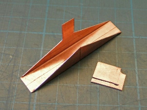
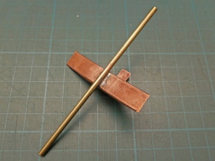
Following the silver soldering, I positioned a brass tube (1/8 “ bore of the type you can buy at model shops) over the centre of the bottom of the copper as shown in the middle picture above. I then very gently heated the copper with the blow torch until it was hot enough to flow some soft solder (as used for electrical work) into the junction between the copper and the brass tube. A bit of soft solder flux will be needed on the joint as well.
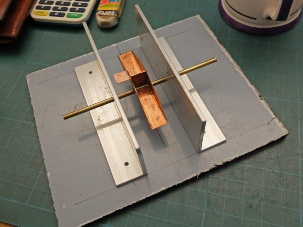
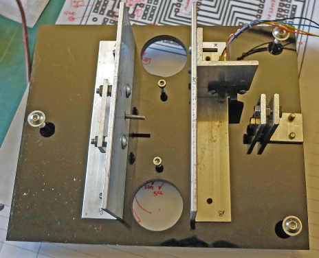
I made a base out of black Perspex and a couple of supports for the buckets out of 3.2 mm thick aluminium angle.
Slot-
Adjustable end stops for the bucket pivot tube. M3 dome head cap screws fit into the ends of the tube and bear against the stops.

Levelling screws.
Stops to limit the movement of the bucket.

Hole to let the water out (will need filter to keep insects out).

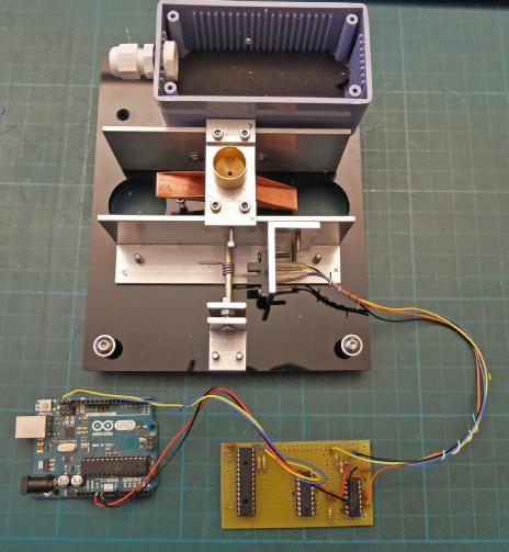
Box for electronics
This is where the collecting funnel will fit. It is a 15 mm plumbing bleed valve. The valve is supplied with a screw on cap. I cut the top of the cap off and turned it into a nut so it can be screwed in place.
This “bridge” can be slid along the support brackets to get the water outlet exactly in the middle of the bucket assembly.
This piece of stiff wire breaks the beam in the slot-
Electronics and Arduino Uno for testing purposes. The electronics counts and stores the number of times the bucket flips. It transmits the number to the Arduino by I2C when requested


Next: the electronics and software.