
 Home
Home


Under construction
Port expander for Feather controller
Next: development of the Raspberry Pi controller and Feather software.
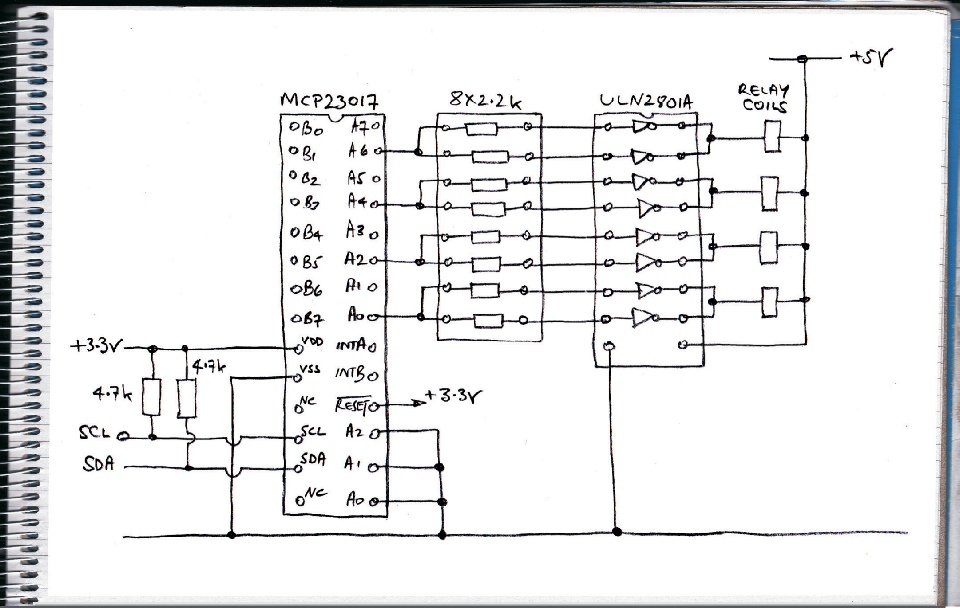
The Feather with the Adalogger add on “wing”uses quite a few pins to communicate with its WiFi and SD card and real time clock features. Once you have interfaced with a few switches, LEDs and a couple of relays you have used up all the available pins. However, there is still I2C (and SPI). The MCP23017 chip provides two 8 bit ports which can be read and written to over I2C. (There is also a version which works with SPI.) The base address is set by three pins allowing 8 devices to be connected. That’s a lot of potential ports (128!). I got this chip here.
In this circuit I am only using four which is a bit of a waste! I am controlling four mains rated relays. I had a ULN2801A to hand so I used that to drive the relays. This version of the 8 way Darlington driver chips needs separate base resistors. I had a DIL 8 x 2.2k resistor package in my box of bits so I used that for th base resistors. I paralleled the Darlingtons in pairs to be on the save side with regard to the current required by the relays.
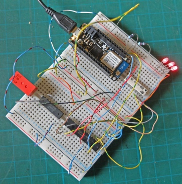
Bread board set up.
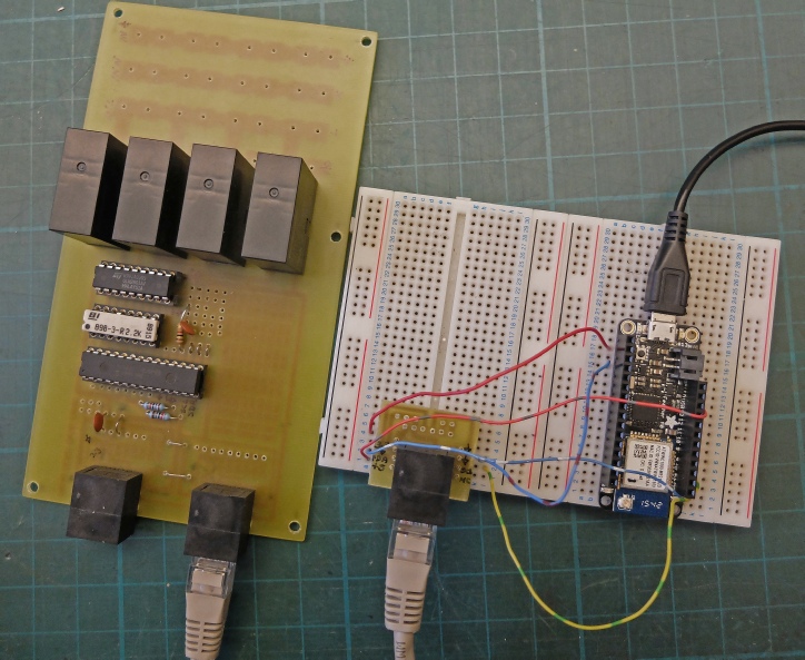
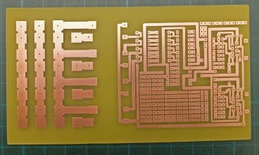
This is the PCB with plenty of “prototyping” area for development (or error correction!)
I’ve decided to solder the mains leads in place rather than use the screw terminals I used on previous projects. Soldering guarantees a good connection which I want to ensure as the relays are rated at 16 amps.
I am using Ethernet cables to connect the I2C as before.
The expander being tested using a Feather on a bread board.
MCP23017 expander chip. 8 x 2.2k ULN23801A Darlington driver.


/*
** MCP23017 16 bit Port Expander
** Created 06 Aug 2012
** This example code is in the public domain.
** www.hobbytronics.co.uk
*/
// This just toggles the outputs on Bank A on and off
// for testing purposes
#include <Wire.h>
const byte mcp_address=0x20; // I2C Address of MCP23017 Chip
const byte GPIOA=0x12; // Register Address of Port A
const byte GPIOB=0x13; // Register Address of Port B
void setup()
{
//Send settings to MCP device
Wire.begin(); // join i2c bus (address optional for master)
// IOCON.BANK defaults to 0 which is what we want.
// So we are using Table 1-
Wire.beginTransmission(mcp_address);
Wire.write(0x00); // IODIRA register
Wire.write(0x00); // set all of bank A to outputs
Wire.write(0x00); // set all of bank B to outputs
Wire.endTransmission();
Wire.beginTransmission(mcp_address);
Wire.write(0x01); // IODIRB register
Wire.write(0x00); // set all of bank A to outputs
Wire.write(0x00); // set all of bank B to outputs
Wire.endTransmission();
pinMode(13, OUTPUT); // on-
}
void loop()
{
Wire.beginTransmission(mcp_address);
Wire.write(GPIOA); // address bank A
Wire.write(B11111111); // value to send -
Wire.endTransmission();
digitalWrite(13, HIGH); // LED flashes to confirm prog is running
delay(500);
Wire.beginTransmission(mcp_address);
Wire.write(GPIOA); // address bank A
Wire.write(B00000000); // value to send -
Wire.endTransmission();
digitalWrite(13, LOW);
delay(500);
}
The program left, courtesy of HobbyTronics, suppliers of the MCP23017, switches the outputs of one side of the expander on and off for testing purposes.
The functionality of this program now needs to be built into the program I have developed for my Feather based timers. These timers currently store on/off timings for two channels with advance functions etc. The data is stored on SD cards in Feather add on boards (Wings).
In the case of the expander boards, I am intending to provide simple (remote) on/off switching (controlled by the user) and the current state of the switches will not be stored in a non-
Depending where you’ve just come from…
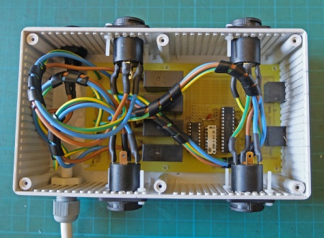
Installation of the pcb in a case.
Fitting a mains cable (in) and four mains sockets (out) takes up a surprisingly large amount of space and the whole system is not exactly tiny! I have opted to solder all the connections rather than fitting spade-
Fuse holder.
Cliffcon FCR2064 touch proof sockets, Rapid Electronics 20-


