 Home
Home


New security lighting controlled by Trinket and real time clock
Turning lights on and off on the basis of light levels can be a bit unpredictable when light levels get pretty low during stormy moments during daylight, especially in winter. A sudden dark event can throw the timing out for a whole day. I have decided to make a system which has on/off periods controlled by a real time clock like the one I have used in my central heating timer.
The system I am thinking of would, in effect, go between the ordinary light switch and the lights. When the light switch was switched on, the lights would go on as normal and go off when the switch was turned off. However, if the switch were left on long enough, the light would go off at a time determined by the program. It would come back on, again under program control, at an appropriate time. The timings would be subject to a random element to enhance “realism”.
In summary:
1) When the light switch is turned on the lights should come on until the next “off” event stored in the program (subject to some randomness).
2) Subsequently, while the switch remained on, the light would turn on and off according to the programmed timings (again, subject to some randomness).
3) When the light switch was turned off, the light should also turn off immediately and remain off.
As an alternative to point 1, when the switch was turned on, the light could remain on for a short period (say 30 minutes) if this coincided with an “off” period. This would avoid the light being on for a long period if the security timings were started in the early morning night time. I am still thinking about this!
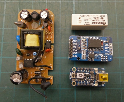
Some of the components needed.
12 volt switched mode power supply extracted from wall plug unit.
Mains-
Real time clock unit.
Adafruit Trinket


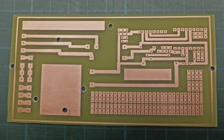
New PCB for this project. There is enough space for the power supply although I could have thought a bit more carefully about where the fixing holes were going to go.
There is a “prototyping” area which probably won’t get used but it saves on etchant! (Also the copper rectangles do the same.)


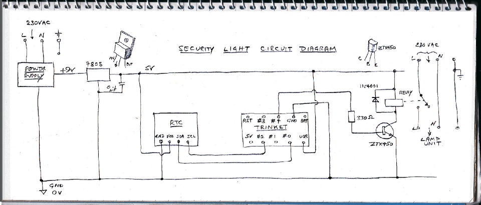
The circuit diagram is pretty straightforward. The power supply is removed from a typical plug in unit. Conveniently the unit screws together with no glue used so it’s very easy to get the circuit out of the case. Wires to the 3-
The relay and clock are the same as the ones used in the central heating timer project (Finder PCB mount relay 5VDC 10A SPDT, Rapid electronics 51-
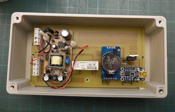
This is what the assembled PCB looks like in the box. The cable entry glands have not yet been fitted in this picture.
Next, software and testing.