Home Julian Rogers Home Alarm circuit Alarm construction

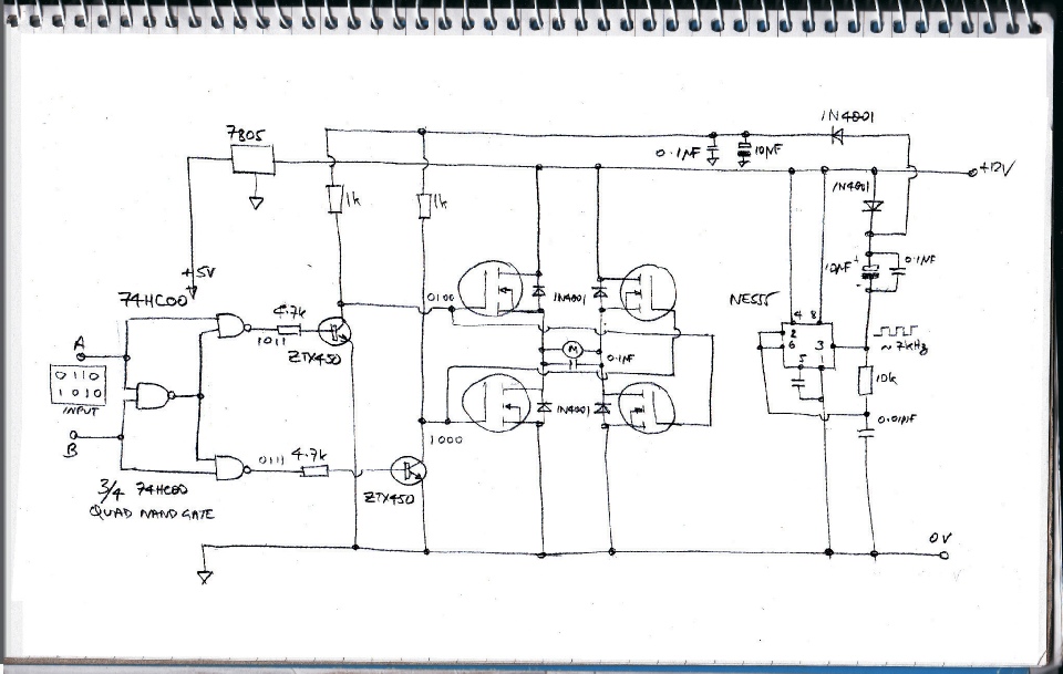
This circuit is needed to control the door locking motors. Since the doors have to lock and unlock the polarity of the supply needs to reverse. The circuit uses 4 mosfets to achieve this. The mosfets tun on in pairs “across the diagonal” so to speak to pass current through the motors in either direction. This could also be achieved with two relays (and a couple of relay drivers - 2 transistors or a bit of a ULN2003 chip, say). The mosfet option is solid-state, no moving parts etc. no contacts to get dirty and burn out etc. but the real advantage of the mosfets lies in the ability to control the speed of the motor by driving it with pulse width modulation (pwm - square waves with controllable mark/space ratio). In this case speed control is not needed and the circuit is not suited to driving with pwm. This would need, as I understand it, mosfet drivers with high current capacity bacause of the high gate capacitance of a power mosfet (see some of my other circuits).

The mosfets need an over-voltage to ensure they are fully turned on. This is provided by the 555 IC which generates a square wave of about 7 Khz which is passed to a voltage doubler circuit comprised of the two 1N4001 diodes and the two 10 micro Farad capacitors etc. The three NAND gates from the 74HC00 IC ensure that all four mosfets can’t be on at once which would lead to a blown fuse! (Follow the logic ones and zeros.)

(I think a suitably low value fuse is essential here (say 10 amps) because there are quite a few failure modes which can lead to the worst case all four mosfets on.)

H-bridge circuit