

Under Construction
Greenhouse monitoring and control system 2
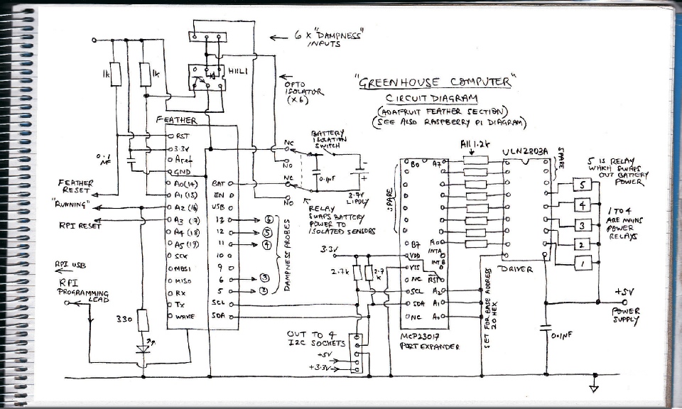
Circuit diagram of the Feather section
The five relays are switched via MCP23017 port expander which communicates with the Feather over I2C. This leaves a lot of inputs/outputs spare (for possible future development). There is an Adafruit library for the Arduino/Feather etc which enables the expander pins to be addressed just like the pins on the processor itself and that makes programming very easy. (Also by wiring up the expander's three address pins either to zero or 3.3 volts on the Feather -
Six of the Feather's own GPIO pins I connect to dampness sensors, one to an LED which I program to flash periodically so I can check at a glance that the Feather has not crashed. This pin also gets connected to the Raspberry Pi so that it can monitor that the Feather is running. Another pin is used to disconnect the power on the Raspberry Pi if it has been shut down (as this is the only way of restarting it). The Feather reset pin is connected to the Pi so that the Feather can be remotely reset.
After taking into consideration the use of some Feather pins by the Feather “Adalogger” board which sits on top of the Feather, that leaves three spare pins for possible future use.
Of the five relays mentioned above, one will be used to control a heater, three to control water valves for irrigation and one to power up the dampness monitors. As mentioned before, I want these to be electrically isolated from the main circuit. I will do this using opto-
The external source of power referred to above comes via the programming lead (usb lead) which connects to the Raspberry Pi. The Pi needs to be active for 5 volts to be present on its usb ports. If it is shut down, power is cut off. If this happens, of course, the Feather will run until its battery runs flat (unless it tries to take a dampness reading in which case it will turn itself off, the relay will release and the Feather will reboot -
The I2C connection is taken out to four sockets. One is taken up by an internal temperature sensor (TMP102) which is fitted into a small box fitted to the outside of the main case to minimise the heating effect of the other circuitry. I expect other connections to involve an external temperature sensor and a rain gauge.
Description
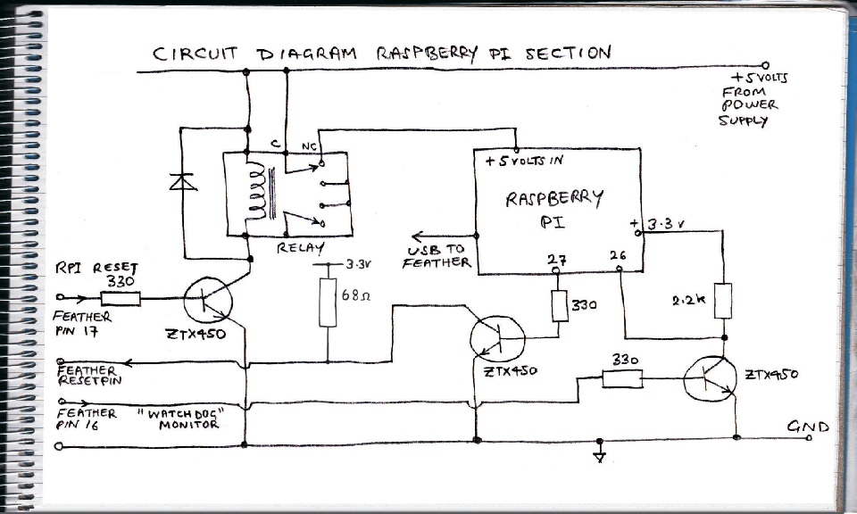
Circuit diagram of the Raspberry Pi section
Description
The Raspberry Pi section is simpler. As mentioned above, its power supply comes via relay contacts so it can be disconnected to reset it following a shutdown. The relay is driven by a ZTX450 general purpose transistor or similar. Pin 27 (Broadcom numbering) connects to the Feather reset pin via another ZTX450 acting as a buffer (this feature has been deleted as explained later). The output of pin 16 on the Feather (pulses on and off to demonstrate the Feather is running and has not crashed) is connected to pin 26 on the Pi, again buffered by a ZTX450.
I think buffers should be used when pins on different processors are connected together. This prevents the case of both pins being set as outputs with one trying to go high and the other trying to go low. I'm not sure whether the outputs of the Pi and the Feather are proof against such contentions but it is better to be safe rather than sorry!

Next: construction.
