


Under Construction
Digital pressure gauge 2
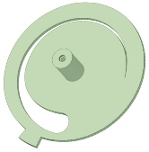

Optical disc
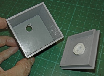
Lid for box
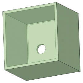
Box
Spacer
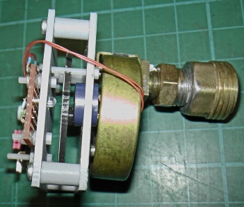
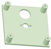
Plate screws onto Bourdon gauge
Screws onto plate
Hole for LDR
Hole for LED


Fits where gauge needle used to go


I used my new 3-
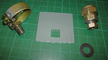
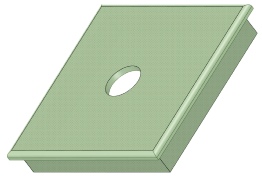
The bottom of the box needed a piece of 3mm aluminium with a square hole to engage with the pipe union on the Bourdon gauge. Plastic would not have had the strength to resist the torque when the inlet pipe was tightened onto the union.
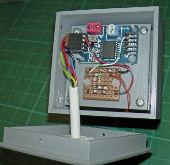
Analogue to digital converter module
Strip board with LED resistor and LDR potential divider resistor


LDR
Disc
LED
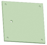
3mm Aluminium plate


2mm hole tapped to M2.5

12mm hole or PG7 size cable gland

Stop

10.5mm hole for 1/8 inch NPT union

2.5mm wall thickness

Screws to gauge

The gauge is held in the box by the male pipe union which is not long enough for a back nut. The spacer allowed the union to be tightened up and have the gauge just secured in the box. 2.1mm thickness worked in this case.
When the NPT union was really tightened up, I found there was no need for the spacer.

// pressure meter test
// press_gauge1
// 15.2.19
// acd2 is connected to the pressure meter
// 0 is ldr, 1 is termistor, 3 is pot used to calibrate gauge
#include "Wire.h"
#define PCF8591 (0x90 >> 1)
int adc0, adc1, adc2, adc3;
void setup()
{
Wire.begin();
Serial.begin(9600);
}
void loop()
{
Wire.beginTransmission(PCF8591);
Wire.write(0x04);
Wire.endTransmission();
Wire.requestFrom(PCF8591, 5);
adc0=Wire.read();
adc0=Wire.read();
adc1=Wire.read();
adc2=Wire.read();
adc3=Wire.read();
adc2 = adc2 -
int c = adc3 * 2;
adc2 = constrain(adc2, 0, 185);
int x = map(adc2, 0, c, 0, 100);
Serial.println(x);
delay(1000);
}
The program/sketch below runs on an Arduino Uno or similar to read the gauge over I2C. The built in potentiometer is used to calibrate the output. I will probably plug the Arduino into an Rpi and oputput the serial from the sketch to the simulation of a gauge in Python/Tkinter as in my wind speed / direction project. Adjusting the pot can set the “normal” pressure to the middle reading of the gauge (ie the “needle” in the vertical position). The gauge reads 0-
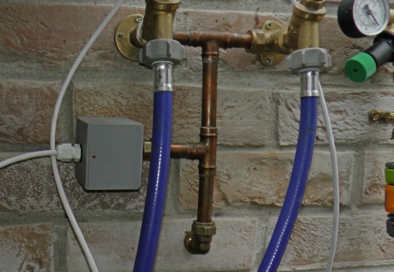
The gauge monitors pressure in the automatic watering system I am trying to develop.
These hoses feed washing machine type valves which are microprocessor controlled (still needs lots of software development!)


Test software
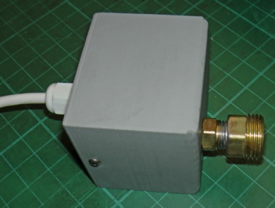
Left: the gauge installed in my greenhouse.
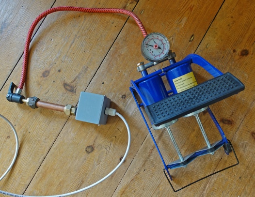
Left: testing the gauge with a foot-
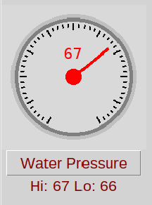
Above: further software development (using Tkinter/Python) enables the pressure to be monitored on a remote computer.
(See here)

NB. If there was a chance the fluid being measured was hotter than a hot cup of tea, I wouldn’t be making parts on the 3-