 Home
Home


Cold start details
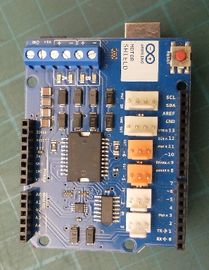
The system uses the Arduino Motor Shield to drive the stepper motor which, by means of a lead screw, can adjust the idle speed on the carb. The shield provides enough power to run the motor without stalling but the maximum speed is not great and probably not enough to provide a rapid enough response in a closed loop idle speed stabilisation system. However, that is not the aim of the system. It is just to gradually reduce the idle speed in response the ambient temperature, the temperature of the engine and partly to the time the engine has been running.
I had tried to implement a starting enrichment system whereby the stepper motor would effectively blip the throttle when the ignition was turned on (and the engine was cold) to get a squirt or two of petrol from the accelerator pumps. This did work but it seemed stupid to have to wait quite a time for the system to do its thing before the starter could be operated when a couple of actual blips on the accelerator pedal was just as good and much quicker.
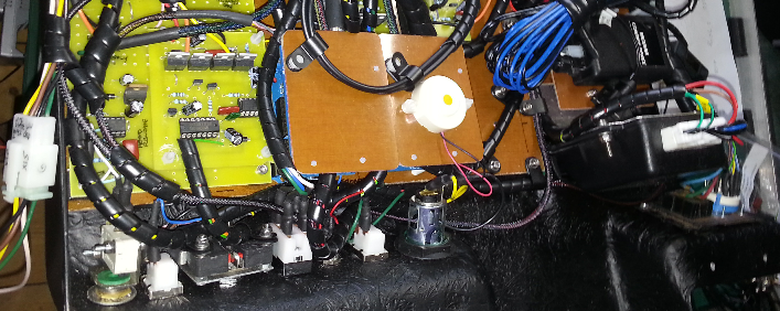
As well as connecting to the stepper motor, the system is connected to two LM35 temperature sensors, two limit switches for the motor (so that it knows where it is at start up), a manual operation/automatic operation switch and a switch to manually adjust the idle speed. There are also a couple of potentiometers which could be read by the software to set any parameters which might turn out to be necessary.
(As I am writing this, I realise that it does sound a bit over-
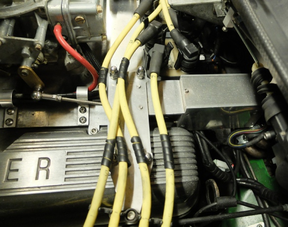
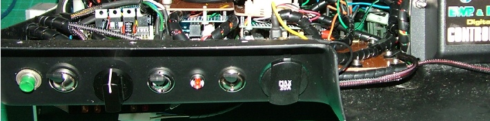
Arduino and motor shield under here.
Manual/ auto switch
Manual idle speed adjuster


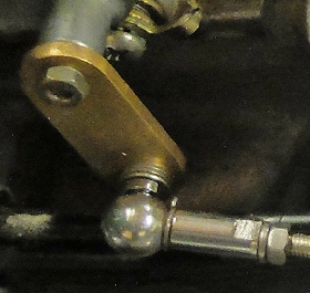
The cold start actuator lives in an aluminium box made from a channel section with two 8 mm thick ends screwed in. The stepper motor is attached to one end of the box and the lead screw passes out here. It is attached to a lever fixed to the remains of the choke mechanism by means of two ball joints (see picture left and below).
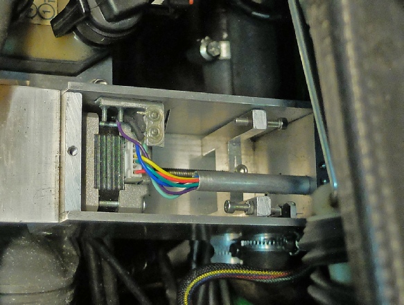
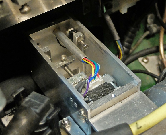
Actuator rod and ball joint

At the other end of the lead screw is an “H” shaped piece of aluminium which can travel back and forth in the box. The aluminium is a reasonably loose fit in the box so that there is no possibility of jamming.
Two micro switches, acting as limit switches, are positioned to that screws on the “H” piece trip them at either end of the lead screw’s travel. The screws on the “H” piece are adjusted to correspond to the extremes of movement required by the lever on the carburettor.
The limit switches, acting with the software, enable the system setup an accurate reference position on startup.
Micro switches

Lead screw
Stepper motor


This unit sits under the dash on the driver’s side (the car is LHD) and contains various bits of electronics such as the security and central locking system.


Next, some circuit and software details…