 Home
Home

Cold start circuit and software
Download a PDF of the Arduino software here.
On powerup the program begins by measuring the air and engine temperature. A value is derived from these temperatures which is used to determine the starting point for the fast idle lever and how quickly it reduces to normal idle. (It should be remembered that this is an open loop system, the actual idle speed at any time is not measured and used in a control feedback loop -
The value is determined by plugging the temperatures into the axes of a two dimensional table (which in actual fact is stored as a single dimensional table of numbers in PROGMEM). I have determined the values in the table by experiment combined with intuition and guesswork so they could be improved, no doubt!
I have also included a “fiddle factor” which can be changed by adjusting a potentiometer. The idea here is that once set up this would not have to be altered. To be on the safe side, I have also included another potentiometer so another parameter could be introduced. However, the software does not use this at present.
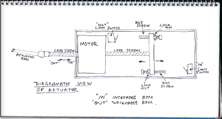
The motor is then moved until one of the limit switches is triggered to establish a reference position.
The software then takes the two values and combines them and the stepper motor moves the idle lever into the appropriate position for starting and subsequently reduces the idle speed as appropriate.
However, if the manual/automatic switch is set to idle, the system just sets a medium idle and waits for manual adjustment.
In the automatic position, the automatic setting is cancelled if the auto/manual switch is changed to manual or the idle adjust is operated. Once in manual mode, automatic mode can only be reset by turning the ignition off and on again -
The system works surprisingly well although there is a few seconds of fast idle when the engine is started from hot which is partly caused by the relatively slow response of the system. The software can increase the number of steps per second but at a certain point the motor will no longer respond and stalls. This is to be avoided as the software expects the motor to be in a particular position because it “knows” the number and direction of the steps it has output. If steps are missed, confusion reigns! Some tweaking of the software would also help to alleviate the hot start situation (which anyway is not the end of the world.)
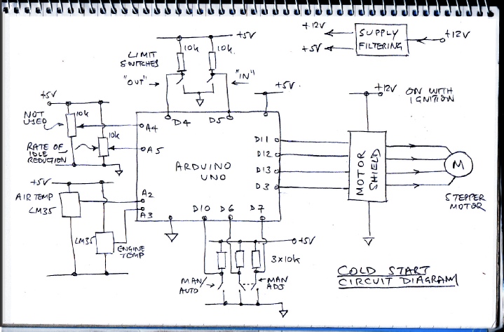
The Arduino has digital inputs from the two motor limit switches, “in” provides the limit for increased rpm, “out” provides the limit for decreased rpm.
It has digital inputs from a automatic/manual selector switch and from a manual increase/decrease rpm. This consists of a control which when turned anti-
The Arduino has analogue inputs from two temperature sensors (LM35) one for air and one for engine temperature. It also has inputs from two parameter setting potentiometers. One sets the rate at which starting rpm decreases after air, engine temperature etc have been taken into account.
The Arduino has 4 digital outputs which are used by the motor shield to enable the stepper motor and turn it in either direction.
Inputs & outputs

Using a prototyping shield to accommodate soldered connections and a few resistors for the switches (these are not strictly necessary) together with the screw connectors on the motor shield means that another purpose built PCB is not necessary. I always like to provide “my own” +5 volt supply rather than rely on the Arduino’s on board regulator as dropping from 13 or 14 volts at the currents which may be required may be too much for it. On this occasion I bought some cheap car USB points, removed the cases and connected them to the Arduinos with short USB cables. (In other circuits, I have used 7805s, chokes, zeners, capacitors and whatnot just in case but the USB points seem to have worked ok here).
For the engine temperature sensor, I soldered connections to the leads of an LM35, insulated them with adhesive-
The air temperature sensor doesn’t need the copper sheath. It can be protected with heat shrink and secured with a plastic P clip in cool air away from the heat of the engine bay.
Circuit construction
Software
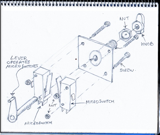
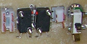
The manual idle speed adjust is made from two micro-
Micro-
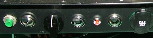
Control knob

Idle speed adjuster switch