


 Home
Home

Under construction
Case for Pi Zero and interface pcb
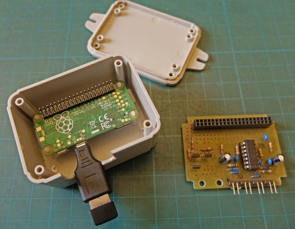
The Pi Zero and the pcb just about fits into a 80 x 60 x 40 case (Hammond RL6115-
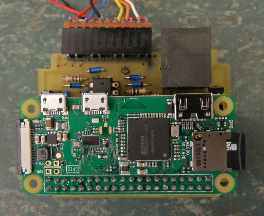
I’ve bolted the Zero to the box with M2.5 nylon screws. The pcb is held in place with the 40 way header.
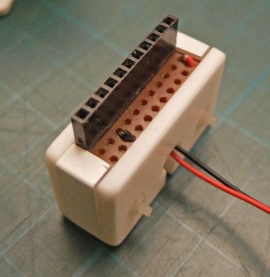
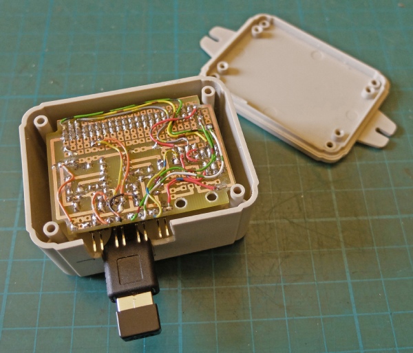
Messy pcb bottom again!
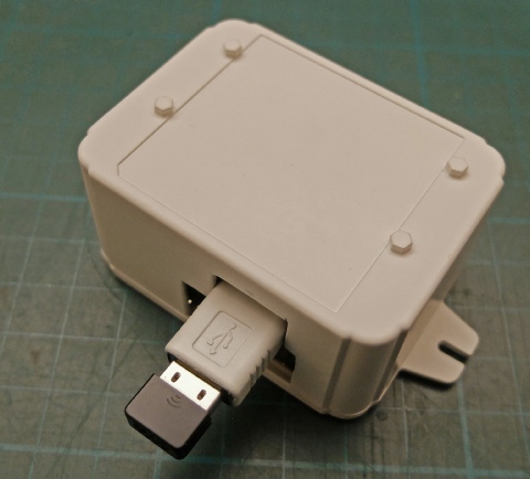
I sprayed the box and the USB adapter white to blend in with the décor in our hall but I chickened out of spraying the wifi dongle!
One of the things which has slowed me down with this project is trying to install the hardware in the most unobtrusive way possible (having taken considerable trouble, a few years ago, to clean up the look of the hall from a decorative point of view).
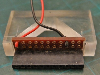
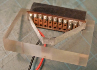
I made a plug to connect up the system. It consisted of a female header soldered to a strip of Veroboard three holes deep. One row of holes is enlarged to 2.5 mm to allow the cables to pass through before being soldered in place as shown in the picture. This provides strain relief for the cables. The strip is gripped in small slots cut in a piece of 5 mm Perspex.
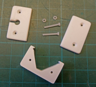
This picture shows the Perspex sprayed white and two covers and M2 nylon screws to hold it all together.
The finished plug. The Veroboard could do with a little sanding down to all the covers to fit tighter.
Next, some test software.
Subsequently, I bought a Pi Zero W which means no WiFi dongle and nothing sticking inelegantly out of the box!
Look, no dongle!
