This project involves making a rev counter for my new mini metal working lathe. This is a project intended to find out what I can do with my new 3-


Under Construction
3-

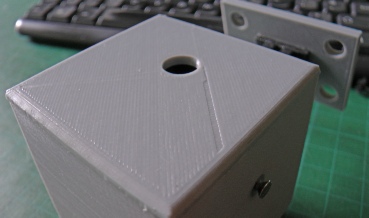
This flaw seems to be associated with the hole. Is it because it is in the side of the print?
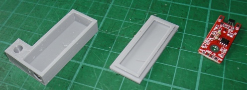
Next, a simple box and lid to house the Hall-
Left shows the module in the box. The cable consists or three wires within some spiral binding. This in nice and flexible. A cable tie is sufficient to hold the binding in place. You can see that the edge needs a little bit of a clean up with a knife or a fine file.
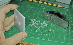
A miniature block plane is also good for cleaning up.
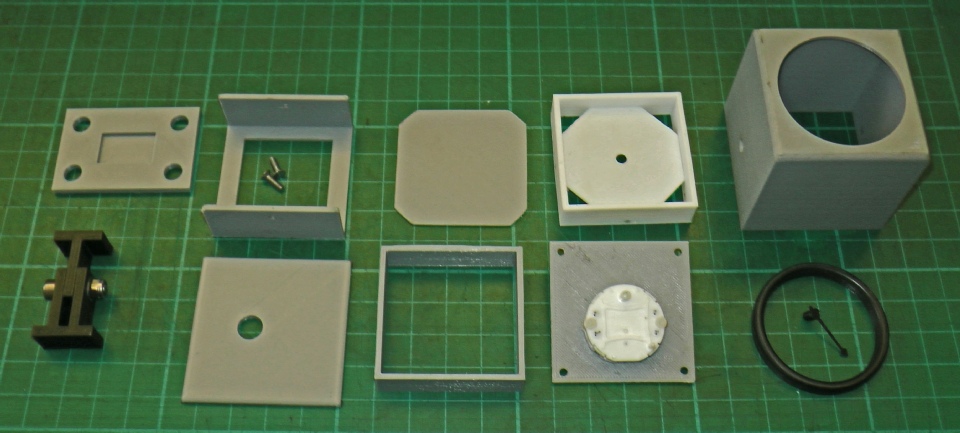
Base (with holes for magnets).
Back of unit in two parts to be glued together.
Paned to mount circuit board.
Spacer with panel on which dial is glued. In two parts which are pinned together.
Case.
Adjustable pedestal (in two parts).
Spacer between motor and circuit board panel.
Panel with stepper motor attached with M2 screws
Meter bezel and indicator needle.


I wanted to make something as a bit of a practice exercise, of reasonable complexity, to establish that I was capable of designing some basic components that would be printed to the right dimensions to fit together correctly. I also wanted to see if the result would look reasonably “shop bought” without doing anything in the way of post-
I would try to incorporate in the designs, as many holes etc. as possible as would be needed but given that it would be a prototype and given my approach to design, which can be summarised as “make it up as you go along”, it was obvious that there would need to be some filing and drilling.
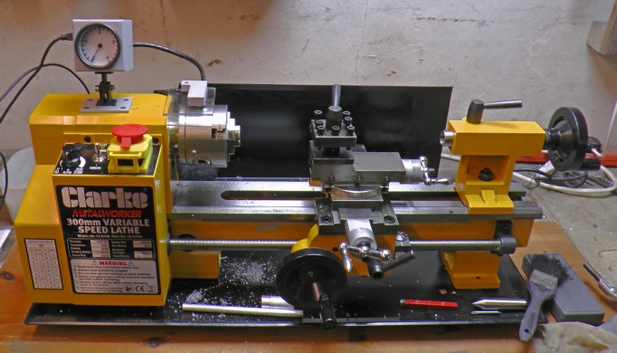
I had just bought a micro metal working lathe with electronic speed control so I thought that a rev-
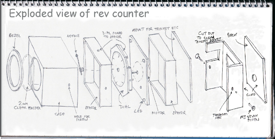
The sketch below shows the various parts of the project. The parts are made 2mm or 2.5mm thick and I allowed 0.25mm clearance all round for the dimensions of the parts which slide into the case. The dial is printed out on transparent inkjet film and glued down with spray mount. I use Tensol No.12 to glue those parts needing gluing.
The picture below shows the manufactured parts. Other than cleaning off any extraneous plastic, I left the parts “as printed”. The exception was the bezel. This looked messy so I sanded it and polished it to a low sheen on a buffing wheel charged with Tripoli compound.
The as printed quality is probably good enough for a utilitarian item with a reasonably consistent texture. However, there are some flaws. Whether they are the result of glitches in the CAD program, the Cura slicing software or software within the printer is not clear.
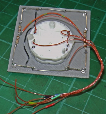
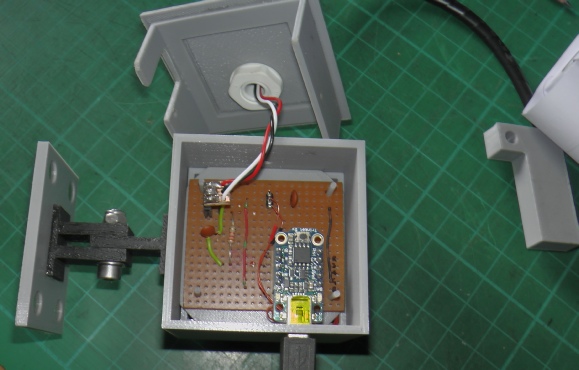
Below are pictures showing some of the electronics and wiring in the gauge itself. On the left are the LEDs and their resisors which illuminate the dial. It’s a lash up but my focus was on the printing! Similarly, on the right you can see I have used strip board (Veroboard) to mount the Trinket etc. taking the easy way out rather than making a pcb.
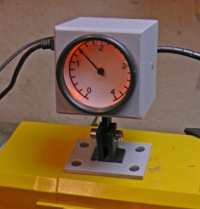
Left is the rev counter and sensor mounted on the lathe using magnets.
A description of the electronics and the software for the project appear on the next page.
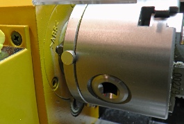
Four magnets on the chuck trigger the Hall sensor. They show no sign of being thrown off by centripetal acceleration. (My maths teacher denied the existence of centrifugal force!)