

// Code for lathe rev counter etc.
// rev_counter4
// stepper type gauge
// 5v Trinket micro (NB this type now deprecated by Adafruit. Use Trinket M0)
// (project to practise using 3-
// 13.1.19
// Stepper Motor VID29-
// -
// -
// -
// -
#include <Stepper.h>
#define STEPS 720 // steps per revolution (limited to 315°)
#define STEPS 720 // steps per revolution (limited to 315°)
#define COIL1 1
#define COIL2 3
#define COIL3 4
#define COIL4 0
// Hall effect sensor input is pin 2 (board has Hall sensor plus comparator)
// create an instance of the stepper class:
Stepper stepper(STEPS, COIL1, COIL2, COIL3, COIL4);
int pos=0; // Position in steps(0-
int pulse;
int val = 0;
int oldVal = 0;
const int timedPeriod = 100; // 0.1 sec, different values can be tried
// const int calib = 40; // adjust to calibrate meter
// at 4000 rpm there are 66.67 revs / sec
// with three magnets there are 2*3 = 6 changes / rev
// so 66.67 * 6 = 400 changes / sec
// in 0.1 sec there are 40 changes which gives the value of calib at 40
const int calib = 53;
// as above but with four magnets, pulses = 2*4 = 8
// 66.67 * 8 = 53 (rounded)
int pulses[5];
int ave;
const int runSpeed = 30; // different values could be tried
unsigned long m; // current millis() value
//-
void setup() {
pinMode(2, INPUT);
stepper.setSpeed(30); // set the motor speed to 30 RPM (360 PPS aprox.)
stepper.step(630); // run motor to max. if not starting at zero,
// motor just stalls
delay(1000);
stepper.step(-
}
//-
void loop() {
pulse = 0;
//count pulses x2 over timed period
m = millis();
while (millis() < m + timedPeriod){
val = digitalRead(2);
if (val != oldVal){
pulse++;
}
oldVal = val;
}
pulse = map( pulse, 0, calib, 0, 600);
constrain(pulse, 0, 630);
// calculate running average of last five readings
// shift up previous results
for(int i = 4; i > 0; i-
pulses[i] = pulses[i-
}
pulses[0] = pulse;
// produce a running average
for(int i = 0; i <= 4; i++){
ave = ave + pulses[i];
}
ave = ave / 5;
//adjust needle to new value
while(abs(ave -
if((ave -
stepper.step(1);
pos++;
}
if((ave -
stepper.step(-
pos-
}
}
}
// end of program -
Electronics & software
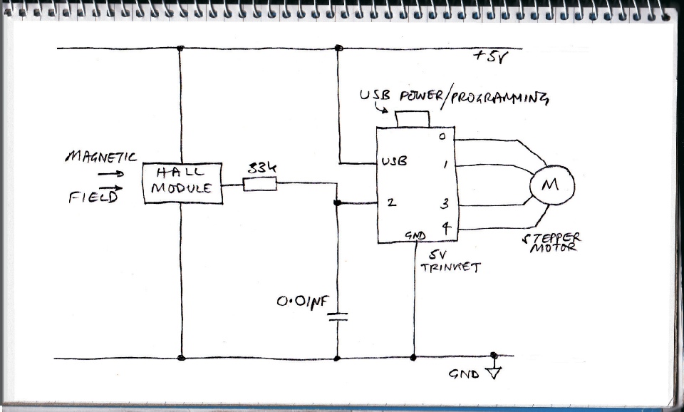
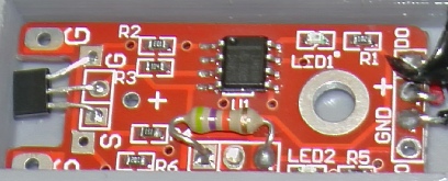
Circuit diagram.
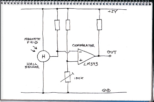
Left is what I guess the circuit diagram for the Hall effect sensor module to be (plus a couple of LEDs and their resistors). As mentioned, I have removed the adjustable resistor and replaced it with a 47k fixed resistor.
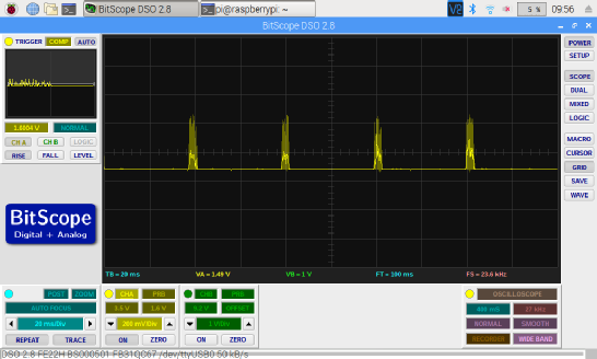
These are the unstable pulses which caused the Trinket to over-
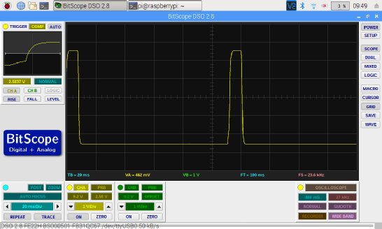
These are the pulses after filtering. I can’t believe that a simple low pass filter can be so effective but there you are!
(The apparent difference in height is the result of different scaling factors and different probes being used for the two traces.)
I also tried passing the comparator output through a Schmitt trigger and monostable pulse generator (see some other projects) but it made no material difference to the response by the Trinket in counting the pulses so I didn’t include that in the final design.)
The hardware makes use of a Hall effect module and an Adafruit Trinket (5v). (This Trinket is now deprecated by Adafruit in favour of the Trinket M0 – see their web site – but I had one of the old sort in my box of bits!) The Trinket can use four of its pins to directly drive a miniature stepper motor designed to power automotive gauges.
The sensor module is widely available on Amazon, Ebay etc. It seems to be manufactured by LC Technology (Chinese company) and feature a Hall sensor and an LM393 comparator. It has a preset potentiometer (wired as a variable resistor) to adjust the sensitivity. I removed this to make the unit more compact. The value of the pot was 100k so I replaced it with a 47k resistor (approximately mid-
I connected the output to a digital pin on my Trinket with a program which counts the number of pulses in a given time. I put a magnet on the chuck of my drill and rotated it in the vicinity of the sensor. (The correct pole of the magnet has to be facing the sensor for it to work.)
I was surprised to find that the pulse count was off the scale compared to what I was expecting given the speed of rotation of the drill. I tried different configurations of software but the result was the same. I began to suspect that the sensor was to blame so I hooked up my BitScope oscilloscope to try to see what was going on. The result seemed to show that when the sensor was triggered, there was a great deal of high frequency noise (see picture) which was causing the false triggering. I presume this is instability in the comparator. I tried a simple R/C filter with values randomly selected and the noise went away (albeit at the expense of a rounding off of the leading edge of the pulse.
Whether this is simply filtering out the noise or causing the comparator to stop producing it in the first place requires further investigation.
Below is the current version of the program. Hopefully, it is self explanatory.
This project has worked surprisingly well! The parts printed out well and all fitted together. It was interesting to see that the lid of the sensor box snapped nicely onto the box without having to make any dimensional allowance. Also, the magnets pushed tightly into the holes which had been printed for them. The plastic must print a tiny bit bigger than the design value and must be a little bit rubbery which is helpful (probably in most cases).
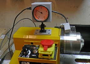
The electronics also seemed to work well. After experimentation, for the lathe speed range of 0-
Conclusion