 Home
Home


Trigger wheel and VR sensor setup 2
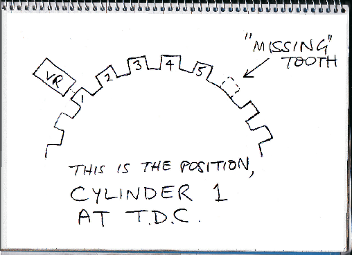
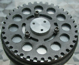
If you chose the same trigger wheel as the one shown above you will notice none of the teeth are missing. To determine which tooth to remove, temporarily install the wheel with the locking screws mid slot and the engine at TDC on cylinder number one. Refer to the sketch on the left. This view is from the front of the car looking towards the rear of the car at the trigger wheel on the front of the engine. Observe which tooth is directly opposite the VR sensor. (Adjust the sensor bracket or the wheel slightly to get the sensor directly centralised on a tooth.) Then the tooth to go will be the sixth tooth, counting clockwise from number one (the tooth opposite the VR sensor).
Removing a tooth in the wheel
Finding top dead centre, or TDC
The first thing to say is that the manufacturer’s TDC marks are not to be completely trusted. The easiest way to find TDC is with the head off as described on another page. However, if the heads are on, a slightly different way will be required. A search of the Internet will reveal several different methods. Here is one I have used.
First, remove all the plugs so that the engine can be easily turned. Take an old spark plug and break or knock out the insulator and conductor. Find a tube which will fit snugly into the remains of the plug. You could epoxy in place if necessary. Then find rod which will fit in the tube allowing it to easily move up and down but without too much wobble. The end of the rod should be reasonably symmetrically rounded. Now you need to fix something on the end of the rod which will prevent it dropping down more than a short distance from the nose of the remains of the spark plug. Screw this into number one cylinder. Then turn the engine clockwise until you feel the piston has just contacted the rod. Draw a line on the pulley assembly where the pointer is with a sharp pencil or perhaps a Staedtler Lumocolor S marker (very fine and very useful for marking -
Since valve timing is not involved here, it’s not necessary to identify the compression stroke.