 Home
Home


Under construction

More radiator software testing

Controller construction next…

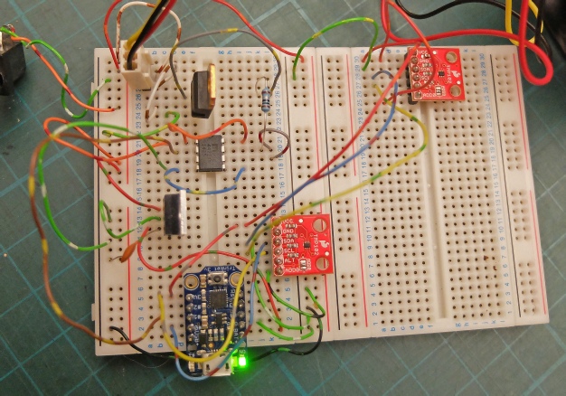
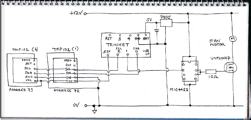
The next circuit uses two temperature sensors. One detects air temperature, the other the radiator temperature. The idea is to turn off the fan if the radiator temperature is below a certain threshold. (This will automatically stop the fans when the boiler is off).
The address selection needs to be different for each TMP102 unit otherwise the I2C communications will not work.. The original TMP102 had pin ADD0 connected to ground. The second sensor has ADDO connected to Vcc (+3.3 volts). This gives addresses 72 and 73 respectively.
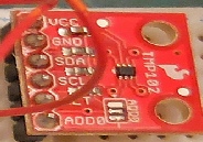
As supplied, the TMP102 breakout board has a solder bridge connecting ADD0 to ground. This must be changed or removed and the connection made externally (otherwise Vcc will short to ground and everything will stop!)
Solder bridge removed

Unfortunately, I just couldn’t get this circuit to work properly. I had a problem when connections to the TMP102 boards were over about 70 mm long -
With the Trinket circuit I may not be able to separate the air temperature sensor and the radiator sensor far enough apart. I may have to think again. Further details of my problems here…
I have decided to go back to the Arduino Uno to power my controller. This makes the unit physically larger but I could incorporate other features such as a readout of sensor temperatures on an LCD screen.

Arduino Uno version
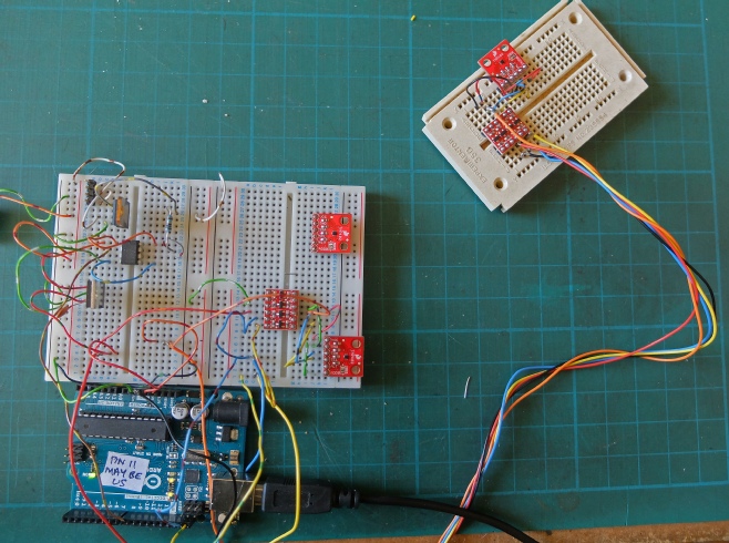
Left is the breadboard for the Arduino powered version. Since the Arduino runs at 5v and the sensors at 3.3v, level translators (Sparkfun) need to be used.
I didn’t have any trouble getting this to work. The advantage of the Arduino over the Trinket is that you have the ability to monitor the sensor values that the program is picking up over the serial link. So it can be seen whether the I2C is transmitting sensible values or not.