

Under Construction
After some time, I began to experience problems getting the data from the original radiometer over I2C. I seemed to be getting false data from the ADS1015 module. Funnily enough, if I tested the radiometer with an Arduino Uno instead of the Feather M0 there seemed to be no problem. Anyway, I wondered if it was something to do with the length of cable I was using to connect the radiometer to the Feather. I connected my Bitscope to the SDA and SCL connections and the waveforms looked far from rectangular. I shortened the cable and that improved matters but the false values apparently received by the Feather remained. I won't go into the details here but the problems got really strange and eventually I decided to give up on the ADS1015 and go for a different approach.
I am now counting and storing the number of pulses from the radiometer remotely and downloading the count over I2C periodically. The total number of pulses will be a much clearer indication of the total radiation from the Sun say, over the entire summer and I can always count over a short period to get an instantaneous value or over a day to get a value which could, for example, be the basis for calculating how long to water the plants at the end of the day or the beginning of the next.
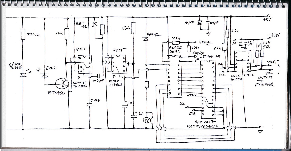
I am now using a Picaxe (from Revolution Education) to count the pulses and measure the voltage from the photo-
The Picaxe has sixteen GPIO pins. I am connecting eight to one of the MCP2017's ports to output the data collected by the Picaxe. Another three inter connections I am using to issue instructions to the Picaxe via the MCP2017 (output count low byte, high byte, pv voltage and reset the counter) and another Picaxe pin gets pulses from the 555s and another, configured as an analogue to digital input, is connected to the pv.
The Picaxe is programmed to count up to 16-
Radiometer Mk2
Problems with the ADS1015 module over I2C

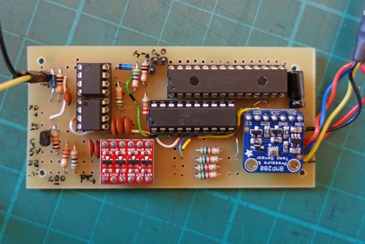
Unfortunately, this new arrangement requires a new pcb. I struggled a bit to get all the new circuitry on the same size pcb as the previous circuit but it was doable albeit with quite a number of wired in links. I really need a double-


New pcb to the same footprint as the previous version.
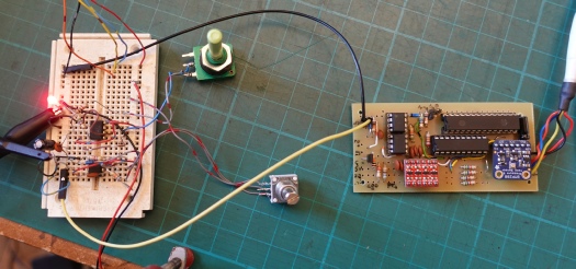
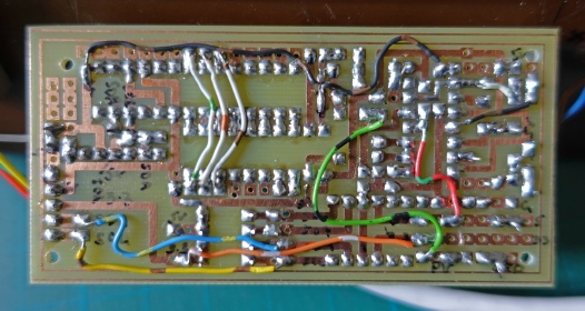
It needs wired in links front and back.
Testing the circuit using a bread-