
Under Construction
Making the 3D printed case for the Pi cam


I started off making the parts to link together two radio control servos. I had found these in my box of bits and they were ten or more years old and although both “standard servos” they were made by two different manufacturers. I had not noticed before that the splined shafts were of two different patterns. One had 23 splines and the other, 24!
I measured the outer diameter of the shafts and drew in the splines, guessing the size of the teeth. I did a test 3D print and luckily one was a good fit the other was tight but would do.
The other parts were relatively easy to design. I kept the prints reasonably flat and joined the parts with glued tongue and groove.
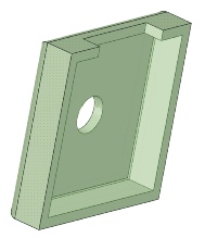
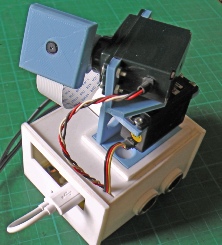
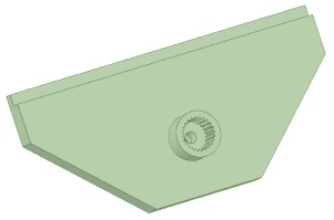
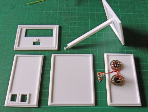
Box for camera with slot for cable.


Next came the box for the electronics. The Raspberry Pi fits onto the lid via standoff pillars. The pcb fits under the Pi, again, via standoffs.
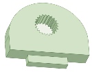
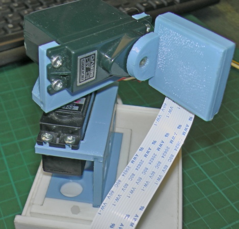
The (blue) servo assembly slides into a frame glues onto the top of the lid.
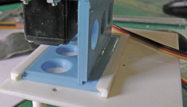
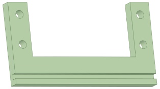
Frame is angled to retain servo assembly.
A retaining piece locks the servo assembly in place.

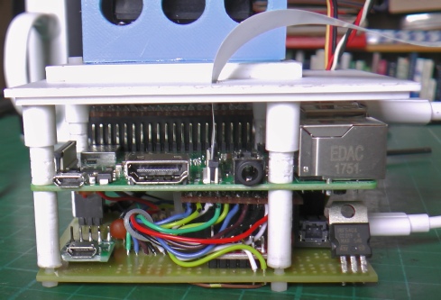
Raspberry Pi
IRF540
Level shifter.
Adafruit Feather (in there somewhere!)
Socket for servo PSU (separate from the micros to be on the safe side).


Left, as mentioned above, the Rpi hangs from the underside of the box lid with the pcb, mounting the Feather, hanging underneath that.
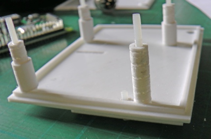
I decided to print the standoffs and the lid all in one piece which did not work out as they suffered poor adhesion every 6 mm or so to the extent that I broke a couple off. I used bits of 2.5 mm nylon screws as dowels and glued them back together. I then made some sleeves to reinforce them.
Sleeve

Bad printing!

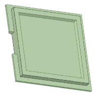
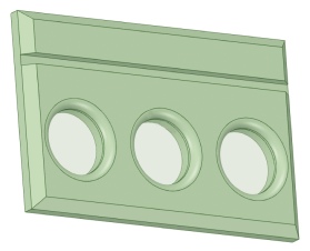
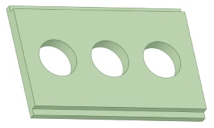
The picture on the left shows the parts of the case minus the lid. The long sides and the top and bottom located in rebates while the ends have slots which clip onto the other parts with a nice tight fit. A square bar passes through the case and prevents the ends detaching.
Sockets for I2C connection.


Software to operate the camera is described on the next page.
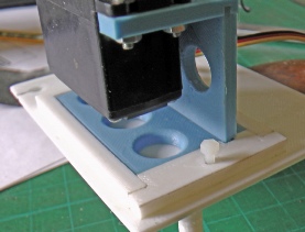
Construction postscript: The Big Heat
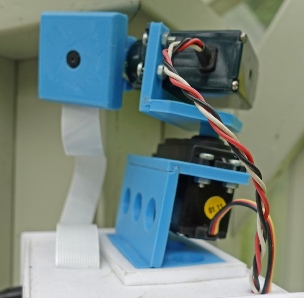
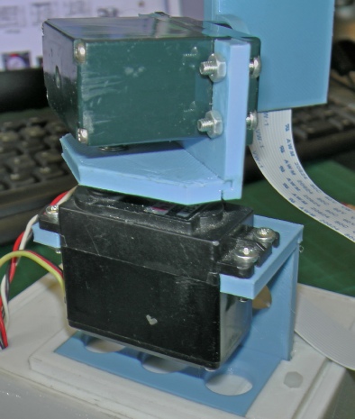
This what happened after a very hot day recently. The heat softened the PLA and the camera took a bit of a lean to the right! Dismantling and putting the blue component in boiling water briefly enabled it to be straightened out. I’ve put a support under the lower (pan) servo to reduce the likelihood of it happening again.
Unfortunately, in a greenhouse surfaces can easily heat up to 50 degrees C or more. One possibility would be to replace blue with white which will reflect more heat but the real answer would be to print in a more heat resistant plastic. ABS looks to be the most practical alternative with “heat resistance” up to 100 deg C according to Neil M Wyatt in his book “3D Printing for Model Engineers”. I haven't tried using it yet. I understand it is more difficult than using PLA.
Leaning!