
Under Construction
Pektron low coolant warning unit explained (hopefully!)

This unit turns on a warning light if a probe in the coolant header tank is above the water level. To complete the circuit, the tank needs to have a second probe connected to the chassis (earth) if the tank is plastic or the tank needs to be connected to the chassis if it is metal.
The unit makes use of a quad NAND gate IC a 4011 or a Scmitt Trigger 4093 version as in the unit shown above (which I take t be a later version not branded “Pektron”. These are cmos logic chips which can operate at supply voltages up to 15 volts. The have very high input impedances and are vulnerable to static.
The circuit can be divided into two parts.
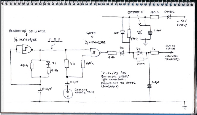
The first part consists of relaxation oscillator which produces a train of square waves. The 0.01 microFarad capacitor starts discharged so the NAND gate’s inputs are low and the output high. The capacitor charges through the 4.7k resistor and the diode. When the input reaches the threshold voltage the output goes low and the capacitor discharges through the 470k resistor (the diode prevents it discharging through the 4.7k resistor. So the positive pulses are much shorter than the zero volt periods in between.
The pulses pass to the inputs of the second gate.
One input is shorted out by the 0.1 microFarad capacitor if the probe is under water and so the output of the gate remains high. If the probe is above the coolant level, both inputs are supplied with the pulses.
With the probe under coolant, the output of the gate is high and has no effect on the following circuitry owing to the diode D2. The output to the latch or bistable (the next part of the circuit) is high via the 470k resistor, diode D3 and the 1k resistor. If the gate’s output pulses low (probe above coolant), the low parts of the output will discharge the 6.8 microFarad capacitor through the 4.7k resistor, the diode D2, and the 820k resistor providing a low enough output to trigger the bistable section of the circuit after a short time. This delay, I think, avoids false triggering due to sloshing in the header tank.
This is my analysis of the circuit. I do not guarantee I am correct about all aspects of the circuit but I think the general drift is correct (again, hopefully!)
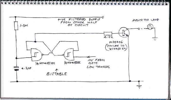
When power is first supplied to the circuit (ignition on), the output of the bistable to the transistor is high, turning the warning lamp on (to show it hasn’t burnt out). Then due to the relative charging rates of the three (?) Electrolytic capacitors and their various resistors, the bistable resets and the lamp goes out, providing the prove is below the coolant (I haven’t quite got my head round the full chapter and verse but this must be what happens).
When the bistable gets a low from the first part of the circuit, the output to the transistor goes high and the lamp turns on. This can only be reset by turning the ignition off (and topping up the tank).
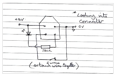
The unit could be tested by connecting the connector up as shown left. The 560 ohm resistor and the LED stand in for the indicator lamp. The switch stands in for the probe in the header tank. Opening the switch simulates low coolant. If the LED does not light, check for transistor failure by measuring the voltage output of the bistable which drives the transistor (point “A” on the top picture). The generation of pulses can be checked by putting an oscilloscope probe on point “B”. This should indicate whether the IC is viable.
A

B

A

B