Home
Home


More details of T-
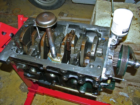
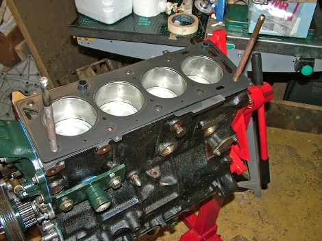
The crank and the block had not been used in a car (they had been used by a garage for practising engine assembly, apparently). However, one of the bores was scratched and so a re-
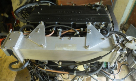
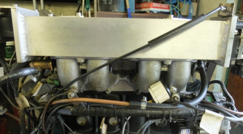
A modified inlet manifold (see below) was required to enable the throttle body to face the front (I think there was a rare Freelander manifold which did this as in that vehicle the installation was front to back, the only one of its kind from Rover). The inlet runners can be split so that it was possible to mate them to a new square section plenum (which was an alloy tube with plates welded on each end. An internal plate along the length of the plenum reducing the section towards the rear cylinder probably would have aided even mixture distribution.)
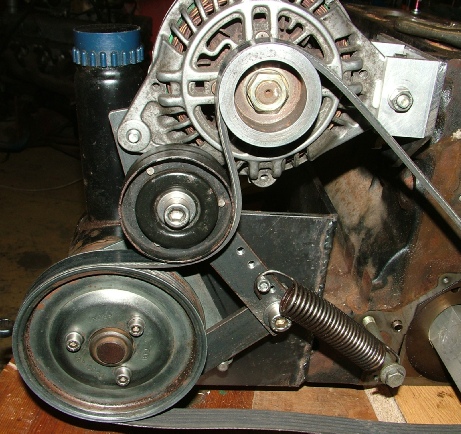
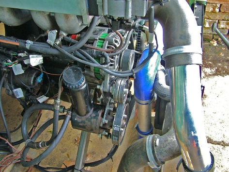
Below left, the alternator and power steering pump had to be repositioned. The water pump and power steering pump shared a housing on the other side of the engine originally. The water pump was replaced by a Davies-
Below, temporary tensioner for drive belt. This might not survive 6000 rpm!
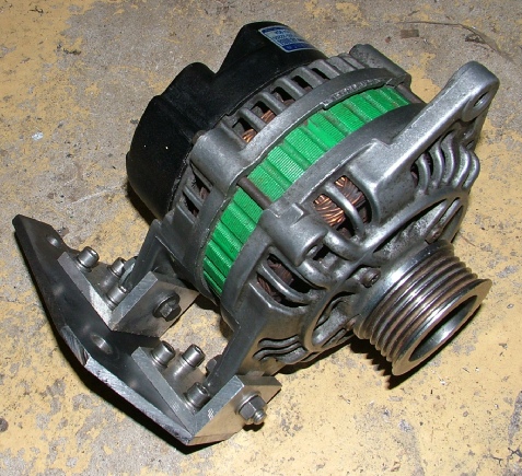
Below, adapter for Japanese alternator. (From a Hyundai Lantra, I think.)
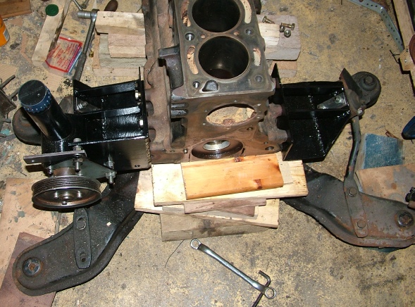
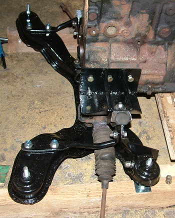
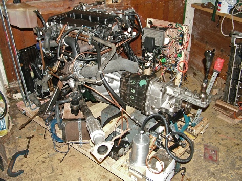
Below, new engine mounts made to fit the engine to a Rover SD1 subframe.

Next: some electrical notes…