Home
Home


Megajolt 3 -
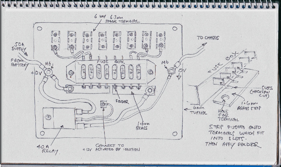
General layout of a distribution board for power to augment or substitute for the original set up is shown below. I make the base out of Tufnol which really looks old school and smells great when you cut it! I drill and tap the Tufnol and secure the components with short socket cap head stainless screws. For example M3 is the size required for the spade terminal strips. The M6 terminals can be made from M6 stainless threaded rod or a M6 countersunk screw screwed in from underneath.
The 6 way terminals can be obtained as 10x Durite -
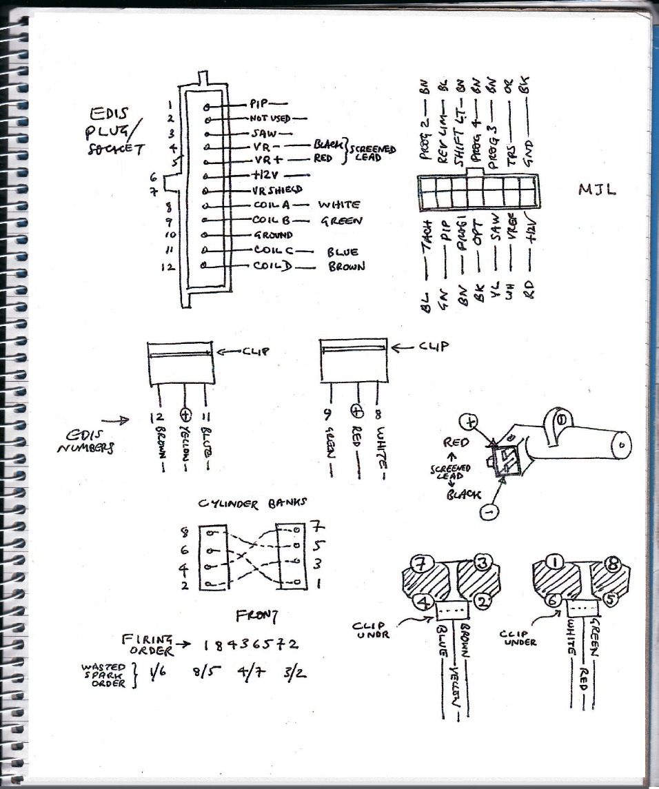
The sketches below show the connections to the EDIS unit and the Ford coil packs as well as the V8 firing order etc. Also the connection to the VR trigger wheel sensor. This should be screened. I used a heavy twin core and screen audio cable. There is a connection for the shied on the EDIS unit and this should be used rather than connecting the screen direct to the chassis.
Details of the trigger wheel and VR sensor follow…
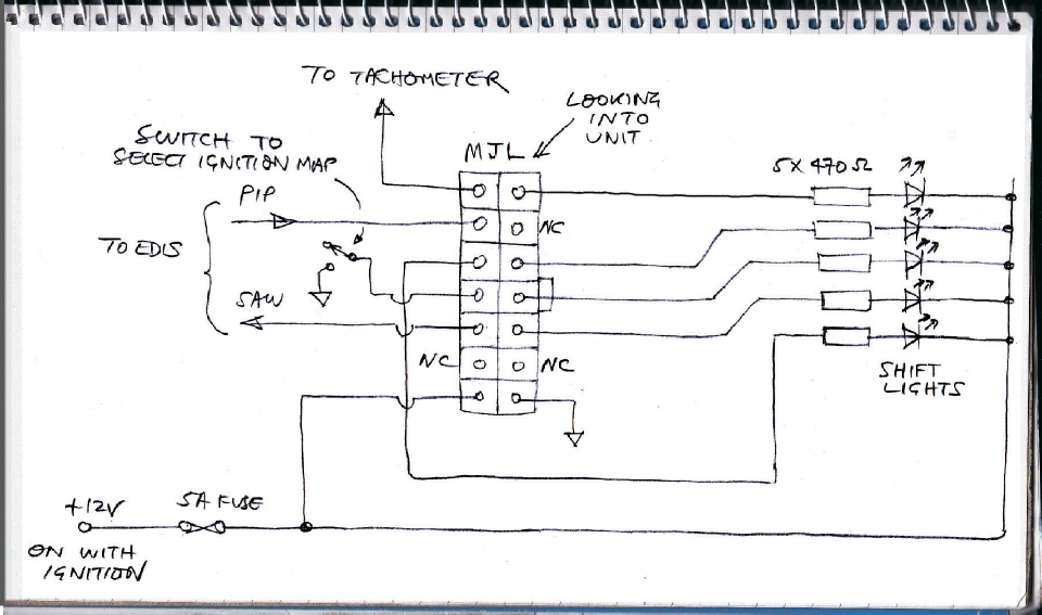
The diagram below shows how I connected five LEDs to act as shift lights. I’m not so sure about this -
The shift lights can be prorammed via the Megajolt software to come on at any rpm (see later).
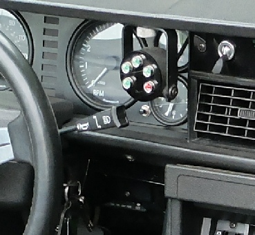
Shift lights
Four green, one red LED in chrome (effect) bezels. (From Maplin)
Body is from a small spotlight but a 50mm instrument cowl could be used
Front is black Perspex