Home
Home


Electronic relays (mosfets) to switch main lights
As far as I can see the TR7 doesn’t have any relays between the light switches and the lights which means that weedy switches like the stalk flasher are switching 10 amps and considerably more at switch on, when the filaments are cold and at low resistance. This is probably why my stalk switch started smoking.
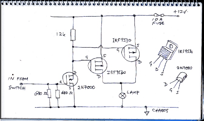
To fix this I built this solid state relay unit to switch the main, dip and fog or driving lamps using mosfets. I also brought in a new supply for these lamps with 10 fuses for each lamp. The original supply to these lamps now just triggers the mosfets.
For simplicity, I used P channel mosfets which can drive loads connected to the chassis without over-
The only problem is that the drain-
I have included 340 ohms resistance between the input and chassis. I believe that cheap (non gold-
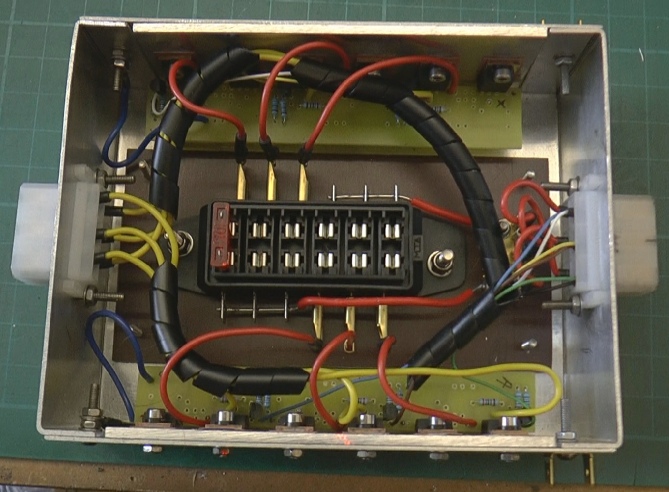
On this occasion I have fabricated the box and lid from 1.5mm aluminium sheet but a die cast box would probably be neater.
I have provided “in” and “out” connectors from Vehicle Wiring Products. They are 6 way 6.3 mm connectors. They would be better if the had a positive lock but have done the job so far. For anything more lively than cruising along (which is all I attempt, officer) cable ties or something similar would be needed.
On the “supply” plug, I have paralleled three poles for the 12 volt supply. The other three are the main, dip, fog 12 volts from the switches.
This circuit needs to be times six, one for each lamp.
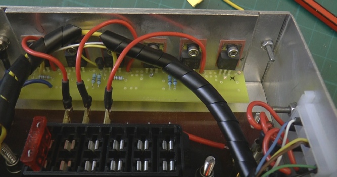
On the “output” connector, there is one pole for each lamp. The mosfets have standard TO220 insulator kits and I have included a bit of 3mm plate for them to be screwed to which is flat and less bendy than the 1.5 sheet used for the box. They should dissipate a tiny wattage under normal circumstances so the heat sink should be more than adequate.
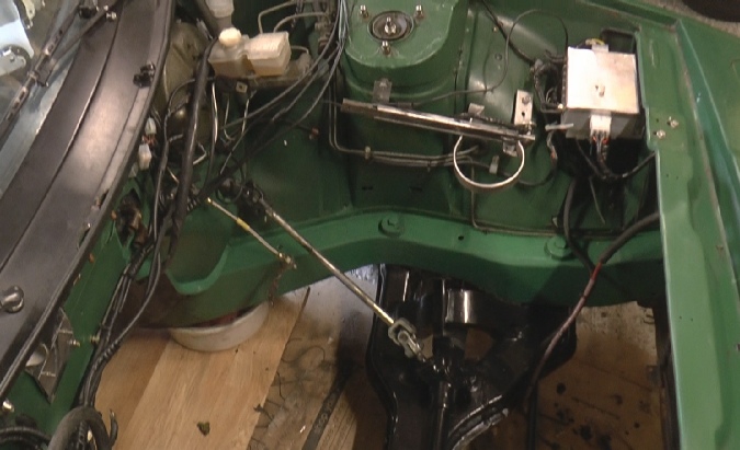
Unit located in engine bay.