
 Home
Home


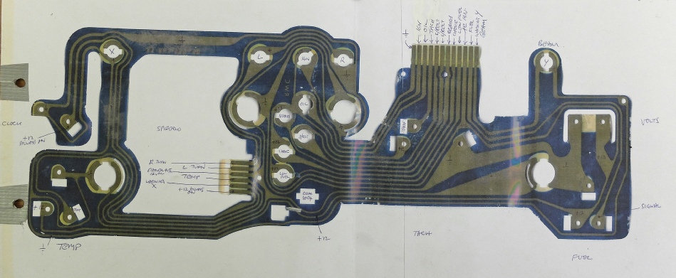
TR7 instrument cluster connections and cable colours
Ignition -
Right indicator -
Left indicator -
High beam -
Oil -
Brakes -
Choke -
Low fuel -
Rear fog -
Tacho sensor -
Speedo sensor -
Fuel sensor -
+ve always on -
+ve ignition -
Illumination -
Chassis/earth -
Instrument cluster cable colours
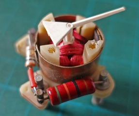
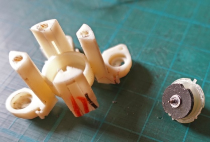
Above: gauge with coils at right angles, coils removed, magnet on needle shaft revealed.
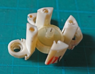
Left: the magnet removed.
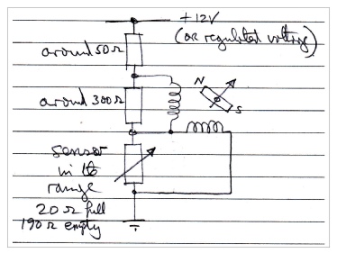
Right: the circuit diagram.
How gauges such as the fuel and temperature gauges work (in cars pre about the year 2000
Within the two coils wound at 90 degrees to each other is a magnet attached to the needle shaft of the instrument. An iron tube round the assembly reduces the influence of stray magnetic fields. This grease on the bearing surfaces of the needle shaft damp the movement of the needle. Adjusting the current through each of the two coils the magnet will line up with the resultant of the two magnetic fields. In the circuit above, this is achieved by the sensor altering its resistance. In the case of the fuel gauge, the sender consists of a float on an arm which slides a wiper over a wire-