 Home
Home


Under construction

Initial Adafruit Fona testing
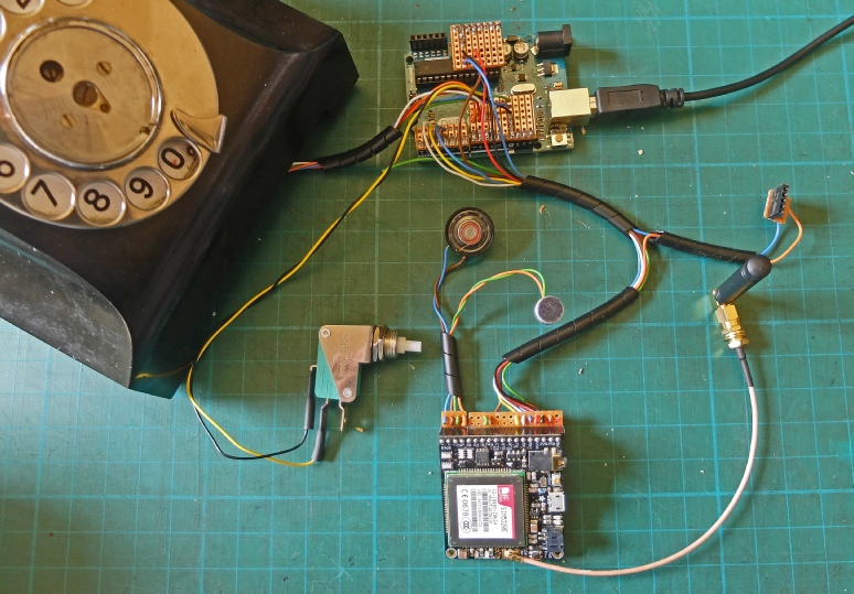
The dial pulse switch and the end of pulse switch (or rest-
Uno rather than Mega used for initial testing.
This will plug into a step up regulator (voltage booster) to power the 5v Arduino from the 3.7v battery (niether shown in picture).
This new antenna will be fitted into the back of the phone case.
This switch will be used to place a call after it has been dialled and will be incorporated into the top of the phone case.


Speaker and microphone.

case 'z': {
for(byte x = 0; x < count; x++){
tele_num_str1[x] = '\0';
tele_num[x] = 0;
}
count = 0;
while(digitalRead(10) == LOW){ // handset off cradle
while(digitalRead(8) == LOW){ // detect current pulse train being generated
delay(20); // allow for bounce
if(digitalRead(9) == HIGH){ // register a pulse
digit++;
while(digitalRead(9) == HIGH){ // wait for end of current pulse
delay(20); // allow for bounce
}
}
}
if(digit != 0){ //10 pulses represents zero
if(digit == 10){
digit = 0;
}
//tele_num[count] = digit; // byte array not needed
tele_num_str1[count] = digit + '0'; // change digit to character
digit = 0;
count++;
if(count > 12){ // limit no of digits to 12
count = 12;
}
}
if(digitalRead(11) == LOW){ // call switch pressed
tele_num_str1[count + 1]= '\0';
Serial.print(tele_num_str1);
Serial.println();
break;
}
}
break;
}
Below is a snippet of code inserted as “case z” into the Adafruit initial testing program for the Fona. It gets a telephone number from the dialler and stores it in the character array “tele_num_str1”. Pressing the call switch completes this process. A slight change to the “case c” procedure inserts the number in the code causing the Fona to make a call. This works fine except that the resulting call seems to pick up a considerable amount of interference in the microphone circuit and no audio emanates from the speaker (the speaker, however, does sound a “bell” when a call is made to the Fona!) These problems remain to be solved!
Following some discussion of the problem with Adafruit, there is a possibility the module is faulty and a new one will be sent to me -
It also turns out, following communications with Adafruit that the Fona Arduino library is missing a number of AT calls which, for example, may be needed to select the audio path. Adafruit will be working to rectify this they tell me. Watch this space.
In the meantime I am starting to work on fitting all the gubbins into the phone. The phone looks enormous but a lot of the internal space is taken up with the dial mechanism and the cradle switches.
After some further research it turned out that my FONA was probably not set to external audio. By loading the drivers for the USB AT connection to the FONA it was possible using the terminal program, Putty, to send AT commands to the FONA to set it up correctly. The available commands are given in the SimTech documentation which can be downloaded from Adafruit. The relevant one is AT+CSDVC=3,1.
This gave me sound in the speaker but the interference was still present. I rewired everything with shorter wires. Eventually, with a 100 nF capacitor across the microphone and the ground plane fitted as described on the next page, the interference was reduced enough to communicate with another phone.
On the basis of this I tried a new much longer but screened cable between the FONA and the speaker and microhone. To my surprise, the interference was reduced unless I brought the microphone close to the FONA and Arduino. Also it made no difference whether I connected the screen to ground or left it floating.
I decided to use the old period plaited cable to connect the FONA to the speaker and microphone installed in the phone’s handset (as described on the next page). I was again surprised to find that the interference had completely gone!
Later I noticed that if I brought the microphone near to the antenna the interference was still there. It was just that with the microphone in the large handset it was physically more difficult to get it in a position to pick up the noise. For this reason, I don’t think it will affect the phone in use as I have configured it. However, it does look as if the microphone might need more RF filtering.
The right socket.
The wrong socket.


Testing
Circuit diagram
Code snippet