


Under Construction
interface
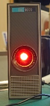
What a great film 2001 is. After all these years, the technology depicted still looks futuristic and the action equals the best that today's CGI can offer (I would go as far as to say it looks more real than CGI). The ape men don't tally with the latest theories about hominid evolution and the ending still slightly baffles me (I've read various explanations but like the definition of existentialism they never seem to stick). Nevertheless, it is one of my favourite films.
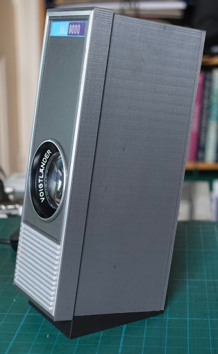
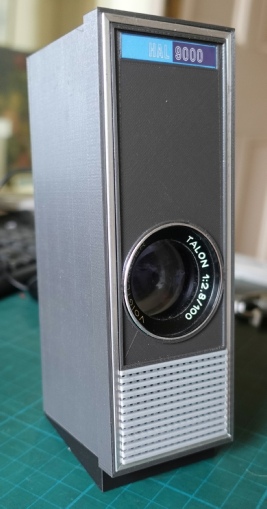
I have wanted to try to emulate the HAL 9000 computer interface with the famous glowing red eye for a long time and now, at last, I've gone and done it!
In this 3D-
The lens is from an old slide projector but an old 35mm camera lens would do. The unit has been scaled to work with the dimensions of the lens and is about half the size of the original, I would guess. Also, the size would be determined by the maximum size which can be printed on my printer and some of the component parts are right on the limit.
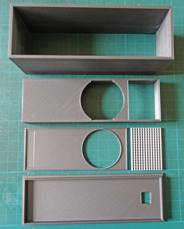
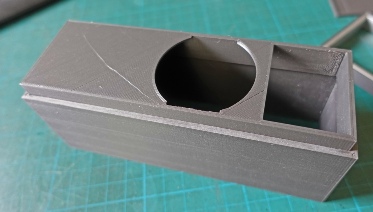
Main case. The thickness is 3.2mm to match the thickness of the aluminium trim (see below).
Case front
Decorative finish for front plus grille. Note shallow recess for logo.
Back, pushes on with aperture for the usb plug.
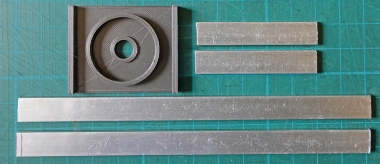
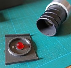
Support for rear of lens (it pushes onto the ring) together with push fit hole for 10mm red LED. Also 10x3.2mm aluminium decorative strip. This needs to be mitred.
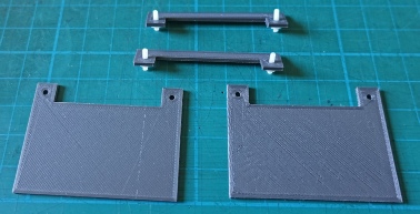
Parts to retain lens and its support plate.
The front is pushed into the case but only so far as to leave a space for the aluminium trim which will be flush with the decorative front panel when it is glued onto the front.
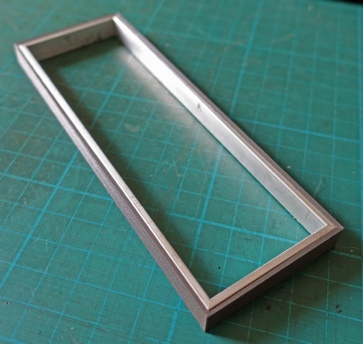
I printed a rectangle of the right inside dimension to hold the mitred pieces of aluminium trim. I used this to hold the trim accurately in place as it was Araldited into position.
I intended to discard it when the glue had set but I preferred seeing just the edge of the aluminium trim so I have left it in place.
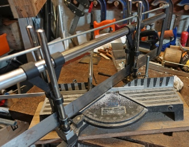
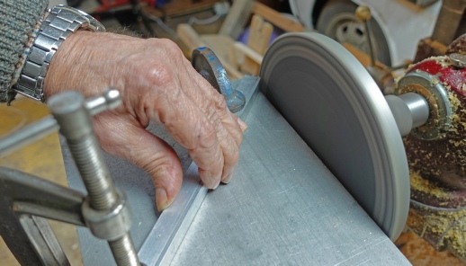
Below left: I cut the aluminium slightly oversize using a mitre saw then, below right: I used a disc sander to get it to the right size as closely as possible. This in many ways is the trickiest part of the build. I could have done better on one bit but at my time of life you have to say enough is enough!
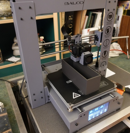
Took about fifteen hours to print the case! Also, it’s quite close to the edge of the plate. It could only have been bigger if the print had been rotated by forty five degrees and then not by much.
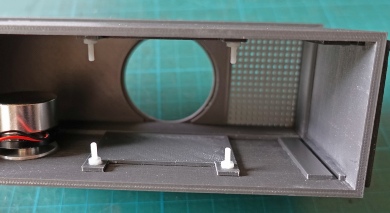
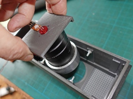
Below left: the support pieces for the lens assembly are glued to the sides of the case. M2.5 screws protrude to locate the locking pieces.
Below centre: inserting the lens assembly.
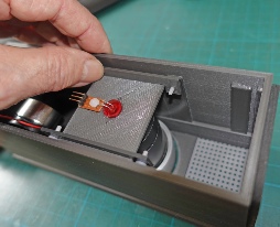
Below right: pushing the locking pieces in place. They rely on being a tight fit on the screws but you could add nuts.

Runners glued on to form slots for electronics assembly.
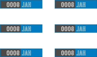
I drafted the HAL9000 logo on CorelDraw9 (it’t ver old but still effective!) In reverse and printed it out on transparent inkjet film so providing a shiny and scratch-

I think you should sit down, take a stress pill and think things over!
There is an updated version on my new website: https://www.newmrr.co.uk