 Home
Home


Under construction

Electrical connections to the fans and making the temperature sensors
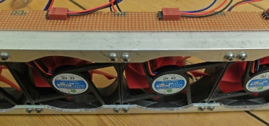
To connect the fans together (in parallel), I purchased a piece of PCB strip board (Veroboard as it once was) 95 x 432 mm from Rapid Electronics (part 34-
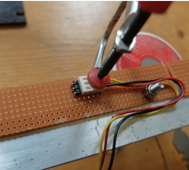
I pared off the guides on the fan sockets with a Stanley knife blade, plugged in the header then fixed it in position on the strip board with a mini G-
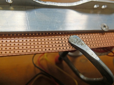
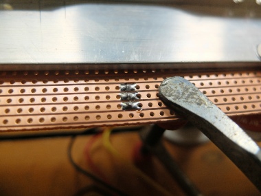
Pins poking through to the copper track side of the strip board ready for soldering.


Twenty times!
Temperature sensors
The system needs a temperature sensor for the room and a sensor for the radiator water so the fans do not run when the water is not hot (that is when the central heating is off).
The room sensor will be the same as the sensor for the central heating controller. The water temperature sensor will also user the TMP102 but will need to clamp onto a 15mm radiator supply pipe. (Later, I thought I might have simplified things a bit and used an LM35 analogue sensor connected to an Arduino analog port. I’ve got a sketch of how that could be done here…)
The pictures show some metal work and some stripboard I used to link the RJ45 socket, the 5v to 3.3v level shifter and the TMP102 breakout board. It’s all a bit of a fiddle and a bit inelegant but it works. A plastic protective case would be nice.
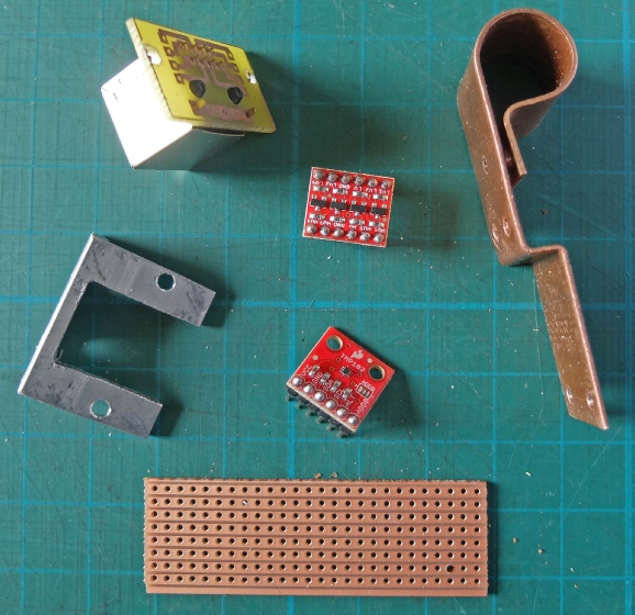
RJ45 on connecting PCB
Copper clamp conducts heat to sensor
Level shifter
Bracket for RJ45 socket
TMP102 breakout board
Stripboard


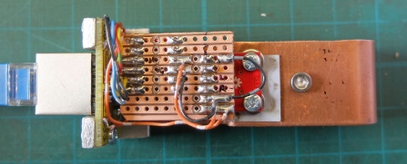
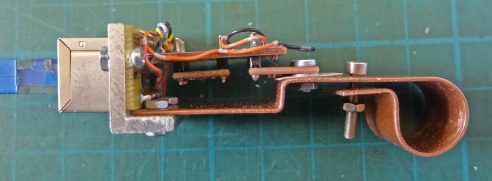
Assembled sensor
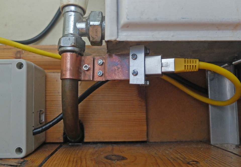
Sensor clamped to radiator pipe