


 Home
Home

Under construction
Electronic door bell/door knocker 2
If I am going to electrify a door knocker, I need a sensor to detect the knocker being knocked.
For this purpose, I am going to use a piezo-
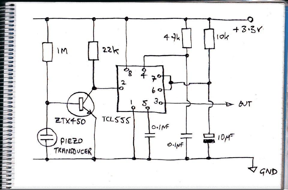
This can be done with the circuit below which is designed to detect a tiny tap on the sensor with a consequently lower output from the sensor. I’m assuming the transistor’s base junction will not be blown by the input from the sensor. Instinctively, I don’t think there is enough energy in a tap on the sensor but I could be wrong!
The circuit uses the CMOS version of the 555 timer integrated circuit. I can't tell you how much I love this IC. It's been around since 1972 and I feel like I've been using it in circuits forever! I recommend “IC 555 Projects” by EA Parr, first published in 1978 and still going strong for about £5.
The 555 is set up in monostable mode and with the values shown (10kOhms and 10microFarads) produces a pulse of about 110 milliseconds when triggered. Triggering is initiated by taking pin 2 below 1/3 of the supply voltage. I'm intending to use this circuit with a 3.3volt micro controller, so less than 1.1 volts will trigger the circuit. The 555 works perfectly at 3.3volts, by the way, in spite of 4.5 volts being specified as the minimum supply. The 4.7k and 0.1 microFarad combination prevent the 555 from triggering when power is first applied. Some power supply decoupling capacitors might also be a good idea.
The piezo transducer's output is amplified by a ZTX450 general purpose transistor. The 1 megaOhm resistor biases the transistor on. The circuit very very sensitive, much more sensitive than I am going to need but such a circuit might be useful in the future.
The sensitivity can be reduced in a number of different ways. Removing the 1M bias resistor leaves the piezo much more to do to get the transistor to trigger the circuit. Reducing the value of the collector resistor from 22k will also reduce sensitivity. Or the transistor could be left out (see later).
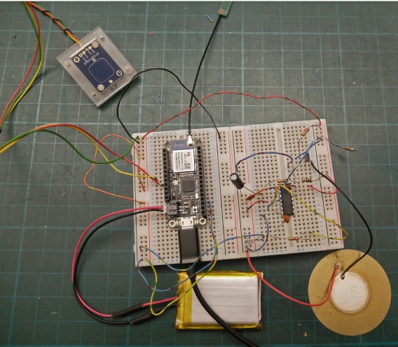
The picture left shows a breadboard with the 555 circuit (it’s a 556 which is the dual version -
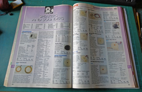
The piezo transducer is a 50mm item from Maplins. I intend to use a 27/1.8 version Maplin code YU87U. Incidentally the 1.8 refers to the resonant frequency of the transducer when it is used to output audio rather than as a sensor. The web site has lost this information but I have a copy of the Maplin catalogue (on paper!) which used to be published each year and which was a very useful reference book in its own right and which has this information. I lament its demise!
(I have used these transducers in the past to provide inputs for an Alesis drum machine.)
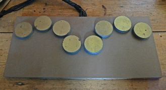
Piezo sensors for drum pads.
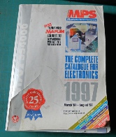
This copy of the Maplin catalogue, 20 years old but still useful!
Next, some construction details…
Piezo sensor on top of roll of tape.
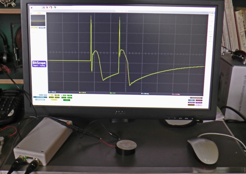
BitScope oscilloscope module
Response from two taps on the sensor. A spike of about 4.5 volts positive followed by about 2 volts negative. This is with a 10 M Ohm input probe. A harder tap could generate 20 or more volts. If the input is a few K Ohms, the voltage is much reduced.